Computer terminal display system and display method for zoom lens target ranging

A computer terminal, zoom lens technology, applied in the direction of program control, installation, etc. in digital output to display devices, sequence/logic controllers

Active Publication Date: 2009-12-09
HENAN COSTAR GRP CO LTD
View PDF3 Cites 4 Cited by
  • Summary
  • Abstract
  • Description
  • Claims
  • Application Information

AI Technical Summary

Problems solved by technology

[0002] The existing target ranging is realized by calculating the time and speed of related auxiliary equipment (such as a laser rangefinder), and the characteristics of the optical lens itself are not well utilized to achieve target ranging. The parameters of the optical lens itself are determined by mathematics Calculation is able to calculate the distance of the target currently observed by the lens

Method used


Image

  • Computer terminal display system and display method for zoom lens target ranging
  • Computer terminal display system and display method for zoom lens target ranging
  • Computer terminal display system and display method for zoom lens target ranging

Examples


Embodiment Construction

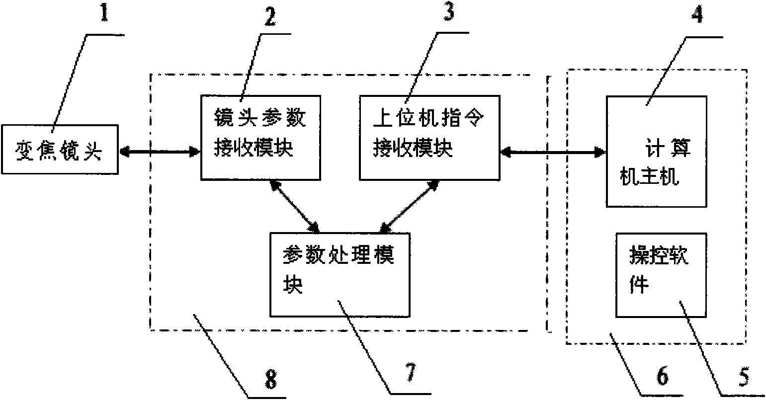
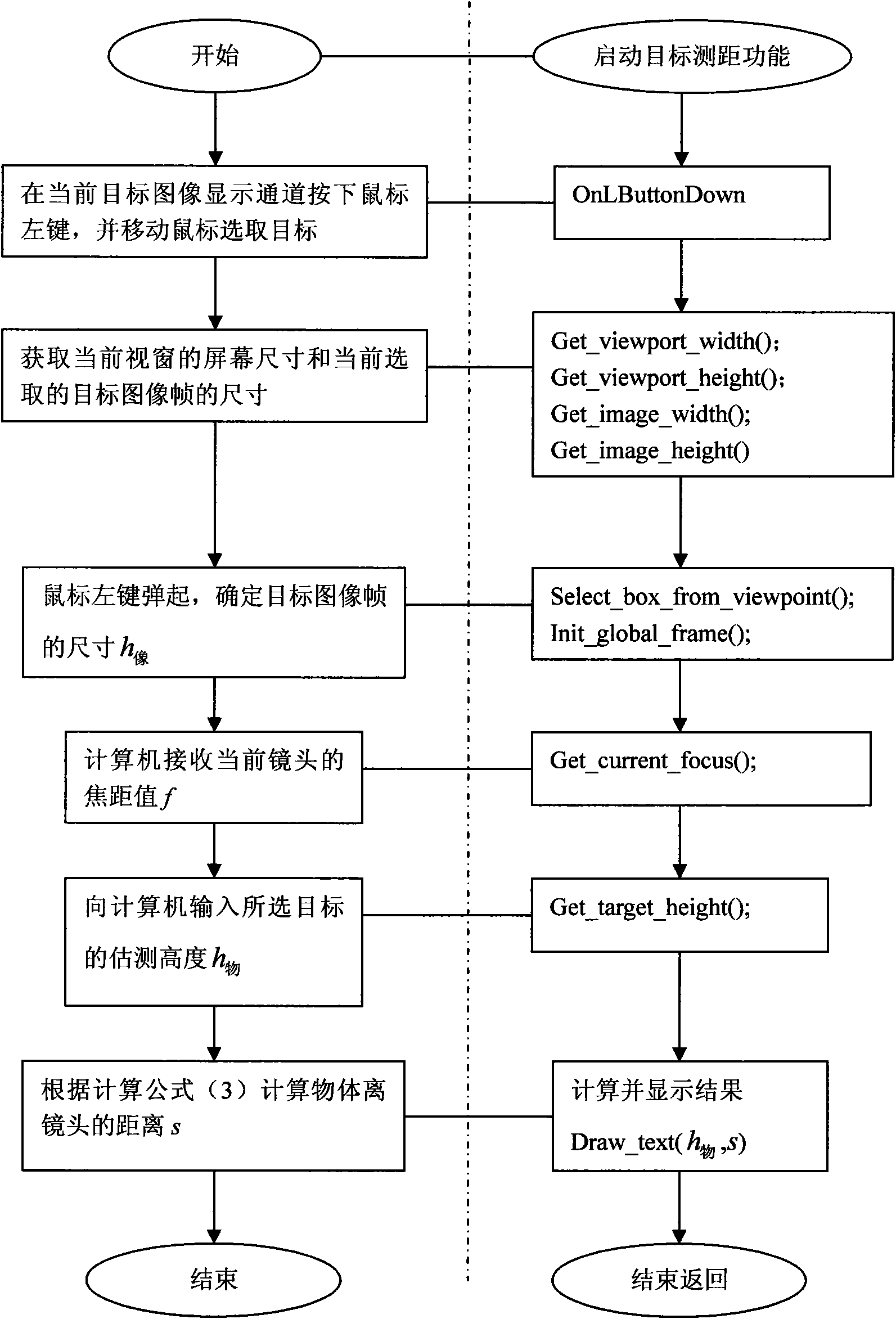
[0013] Such as figure 1 The shown computer terminal system for zoom lens target ranging has a zoom lens 1, which is connected to a lens parameter feedback control system 8, and the output of the lens parameter feedback control system 8 is connected to a computer display terminal system 6, wherein the lens parameter feedback control system 8 is composed of three parts: lens parameter receiving module 2, parameter processing module 7, and host computer command receiving module 3. Lens parameter receiving module 2 is connected to parameter processing module 7, parameter processing module 7 is connected to host computer command receiving module 3, and computer terminal display system 6 includes a host computer 4, a display, and control software 5. The host computer instruction receiving module 3 is connected to the host computer 4. Such as image 3 The computer terminal display method of the zoom lens target ranging shown is realized by the following methods: 1. First select the targ...


PUM


Abstract

The invention discloses a computer terminal display system and a display method for zoom lens target ranging. The display system comprises the zoom lens; wherein, the zoom lens is connected with a lens parameter feedback control system; an output terminal of the lens parameter feedback control system is connected with a computer display terminal system; the lens parameter feedback control system comprises three parts including a lens parameter receiving module, a parameter process module and an upper computer instruction receiving module; the lens parameter receiving module is connected with the parameter process module; the parameter process module is connected with the upper computer instruction receiving module; the computer terminal display system comprises a computer mainframe, a monitor and control software; the upper computer instruction receiving module is connected with the computer mainframe. The functional error of target ranging realized by the display method is controlledwithin 1% of the actual distance and the results can be intuitively, effectively and rapidly displayed on the computer terminal.

Description

Technical field [0001] The invention belongs to photoelectric product technology, and in particular relates to a computer display terminal system for zoom lens target ranging and a display method thereof. Background technique [0002] The existing target ranging is achieved by calculating the time and speed of related auxiliary equipment (such as laser rangefinder), and does not make good use of the characteristics of the optical lens itself to achieve target ranging, and the parameters of the optical lens itself are through mathematics Calculation is able to calculate the distance of the current observation target of the lens. With the rapid development of computer display technology and automatic control technology, it is a very promising development direction to use the combination of computer and optical lens to expand the function of optical lens. Summary of the invention [0003] In order to solve the above-mentioned defects in the prior art, the purpose of the present inv...

Claims


Application Information

Patent Timeline
IPC IPC(8): G02B7/04G05B19/04G06F3/14
Inventor 侯米娜吕瑞云张锐
Owner HENAN COSTAR GRP CO LTD
Why Eureka
Try Eureka