Liquid nano-shearing machine

A shearing machine and nanotechnology, applied in mixers, mixers with rotating stirring devices, dissolution, etc., can solve problems such as unsatisfactory actual effects, simplicity, and complexity, and achieve simple structure, wide application, and good effects Effect

Inactive Publication Date: 2009-12-16
易会球
View PDF2 Cites 10 Cited by
  • Summary
  • Abstract
  • Description
  • Claims
  • Application Information

AI Technical Summary

Problems solved by technology

[0003] They all adopt the working principle of shearing mechanical impact, but their structures, such as the positive and negative impeller set

Method used


Image

  • Liquid nano-shearing machine
  • Liquid nano-shearing machine
  • Liquid nano-shearing machine

Examples


Embodiment Construction

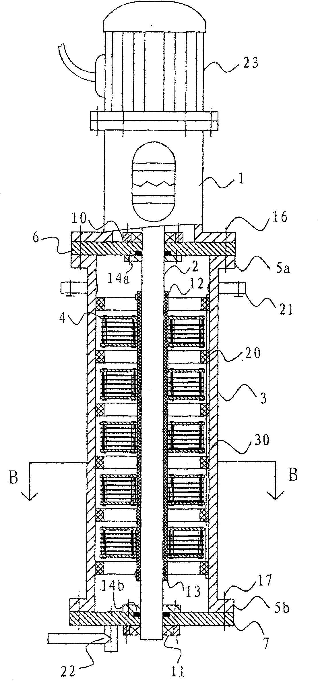
[0035] Referring to the accompanying drawings, the liquid nano-shearing machine of the present invention includes a cylinder body 3 composed of a cylindrical side wall and an upper cover 6 and a lower cover 7 at both ends of the cylindrical side wall, and the two ends of the cylindrical side wall are respectively equipped with upper flanges 5a and the lower flange 5b are respectively connected with the upper cover 6 and the lower cover 7 through upper flange bolts 16 and lower flange bolts 17.

[0036] The liquid inlet 21 is arranged on the cylindrical side wall close to the upper cover 6 , and the liquid outlet 22 is arranged on the lower cover 7 .

[0037] The top surface of the upper cover 6 is provided with a motor base 1, and the motor 23 is fixed on the motor base 1. The main shaft 2 connected with the output shaft of the motor 23 is provided inside the cylinder body 3, and the other end of the main shaft 2 extends into the cylinder body 3 and penetrates the Loam cake 6 ...


PUM


Abstract

The invention discloses a liquid nano-shearing machine, which comprises a cylinder body with a liquid inlet and a liquid outlet, wherein a main shaft externally connected with an external driving mechanism is arranged in the cylinder body; the outer wall of the main shaft is fixed with a shearing device for shearing materials; the shearing device is formed by sleeving a plurality of rotary bodies on the outer wall of the main shaft sequentially; and each rotary body comprises a bolt sleeve sleeved on the outer wall of the main shaft, an upper rotary body sheet and a lower rotary body sheet which are fixedly connected to the outer walls of both ends of the bolt sleeve and a plurality of shearing blades arranged between the upper rotary body sheet and the lower rotary body sheet. The liquid nano-shearing machine uses a large number of blades arranged in a staggered mode to make the inner part of the cylinder body have no blind angle and ensure that every drop of liquid is shorn sufficiently. A plurality of ring-shaped baffle plates form turbulence easily to ensure that the liquid passing through each rotary body continuously is shorn and mixed repeatedly. A plurality of socket-and-spigot rotary bodies have the advantages of simple structure and convenient installation. The liquid nano-shearing machine has a wide application range, a good liquid emulsification effect and a high nanometer magnitude of a water mass particle size, and is suitable for processing multiple liquid-state mixtures.

Description

technical field [0001] The invention belongs to a mixing and shearing machine with a rotary shearing and stirring device in a fixed container, in particular an emulsifying device for performing nano-shearing and mixing in a tube cavity. Background technique [0002] There are many kinds of mechanical emulsification devices. For example, the "rotary impact type fine, uniform and emulsifying device" of Chinese patent 02112974.6 is provided with a housing, which is mounted on the base, has a material inlet and a material outlet on the housing, and a power shaft is housed in the housing. Rotating impellers are installed on the power shaft, and the rotating impellers on the power shaft include forward-rotating impellers and reverse-rotating impellers, and feeding impellers are also installed on the power shaft in the feed inlet. Another example is the "high-shear diesel emulsification device" disclosed in Chinese patent 96212548.2, which is used for diesel emulsification. Accor...

Claims


Application Information

Patent Timeline
IPC IPC(8): B01F7/16B01F3/08
Inventor 易会球
Owner 易会球
Why Eureka
Try Eureka