Backlight module press equipment and use method thereof

A technology of backlight module and pressing equipment, applied in punching machines, presses, manufacturing tools, etc., can solve the problems of insufficient pressing, backlight module color light, insufficient strength, etc., to reduce labor costs, press The effect of tight and suppressing the generation of colored light

Inactive Publication Date: 2009-12-16
SHANGHAI CHENXING ELECTRONICS SCI & TECH CO LTD
View PDF0 Cites 9 Cited by
  • Summary
  • Abstract
  • Description
  • Claims
  • Application Information

AI Technical Summary

Problems solved by technology

[0003] The technical problem to be solved by the present invention is to overcome the disadvantages in the prior art that when the backlight module is press-fitted to the bracket and the light guide plate by manpower, it is easy to appear that the force is not enough or the pressing is not in place, which will cause the backlight module to produce colored light. A backlight module pressing device and its use method which use a foot switch to control the up and down movement of the cylinder, thereby completing the tight pressing of the backlight module and effectively suppressing the generation of colored light in the backlight module

Method used


Image

  • Backlight module press equipment and use method thereof
  • Backlight module press equipment and use method thereof
  • Backlight module press equipment and use method thereof

Examples


Embodiment Construction

[0030] The preferred embodiments of the present invention are given below in conjunction with the accompanying drawings to describe the technical solution of the present invention in detail.

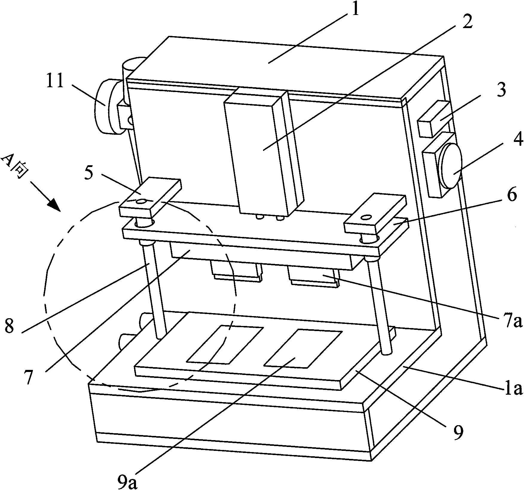
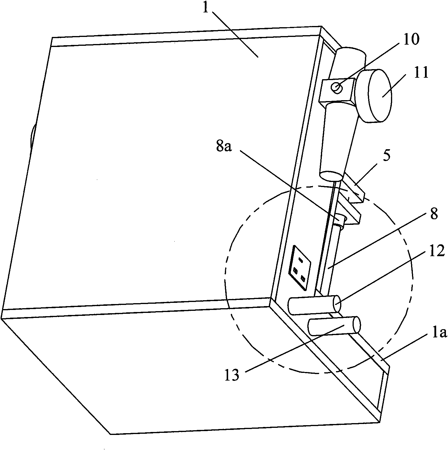
[0031] Such as Figure 1 to Figure 4 As shown, a backlight module press-fitting equipment includes: a box body 1 with a workbench 1a, an upper platen 6 that can run up and down, a lower platen 9 fixed above the workbench 1a, and two The guide rail 8 between the pressing plate 6 and the lower pressing plate 9, the lower end of the guide rail 8 is fixed on the workbench 1a, and the upper end passes through the upper pressing plate 6 and is fixed on the box body 1 through a guide rail fixing plate 5 to prevent the upper pressing plate from 6 slides out from guide rail 8 when running upwards. The connection hole between the upper platen 6 and the guide rail 8 is provided with a connection hole, and the upper end of the guide rail 8 passes through the connection hole and is fixed on the box ...


PUM


Abstract

The invention discloses backlight module press equipment and a use method thereof. The equipment comprises a box body, an air cylinder, an upper press plate, a lower press plate, two guide rails, an air control unit and an electric control unit, wherein the box body is provided with a working platform; the air cylinder is fixed at the upper side of the box body; the upper press plate is connected with the air cylinder and can run up and down; the lower press plate is fixed on the working platform; one end of each guide rail is fixed with the working platform after penetrating through the lower press plate, and the other end of each guide rail is fixed on the box body after penetrating through the upper press plate; the air control unit controls the air cylinder to run up and down along the guide rails; and the electric control unit controls an air loop switch of the air control unit. The equipment can more tightly press a backlight module on the premise of manpower cost reduction and no any adverse impact generation, thereby effectively inhibiting the generation of light in the backlight module.

Description

technical field [0001] The present invention relates to a lamination equipment and its use method, in particular to a lamination equipment for backlight module and its use method. Background technique [0002] In the backlight module, the backlight module that provides the light source is glued to the bracket and the light guide plate with double-sided tape. The traditional process is to rely on pure manpower for lamination, so there will be problems such as insufficient lamination, unevenness or insufficient strength, which will easily cause colored light to appear on the backlight module, thereby affecting the visual effect of the whole machine. Contents of the invention [0003] The technical problem to be solved by the present invention is to overcome the disadvantages in the prior art that when the backlight module is pressed onto the bracket and the light guide plate by manpower, it is easy to have insufficient force or the pressing is not in place to cause the backl...

Claims


Application Information

Patent Timeline
Patent Type & Authority Applications(China)
IPC IPC(8): B30B1/38B30B15/16
Inventor 阳盛华莫传标
Owner SHANGHAI CHENXING ELECTRONICS SCI & TECH CO LTD
Why Eureka
Try Eureka