Hydraulic trash remover for bottom grid diversion dam of power station

A kind of cleaning machine and hydraulic technology, applied in the direction of earth moving machine/shovel, marine engineering, construction, etc., can solve the problems of lack of economic benefits, labor and time, waste of water resources, etc.

Active Publication Date: 2009-12-16
HUBEI XINGFA CHEM GRP CO LTD
View PDF0 Cites 4 Cited by
  • Summary
  • Abstract
  • Description
  • Claims
  • Application Information

AI Technical Summary

Problems solved by technology

[0002] At present, the bottom barrier dam of the power station is commonly used to clean the sewage manually, which is labor-intensive and time-consuming. Moreover, it is impossible to clean the sewage manually when the flood comes. It can only be cleaned after the flood subsides, which wastes water resources. not get better economic benefits

Method used


Image

  • Hydraulic trash remover for bottom grid diversion dam of power station
  • Hydraulic trash remover for bottom grid diversion dam of power station
  • Hydraulic trash remover for bottom grid diversion dam of power station

Examples


Embodiment Construction

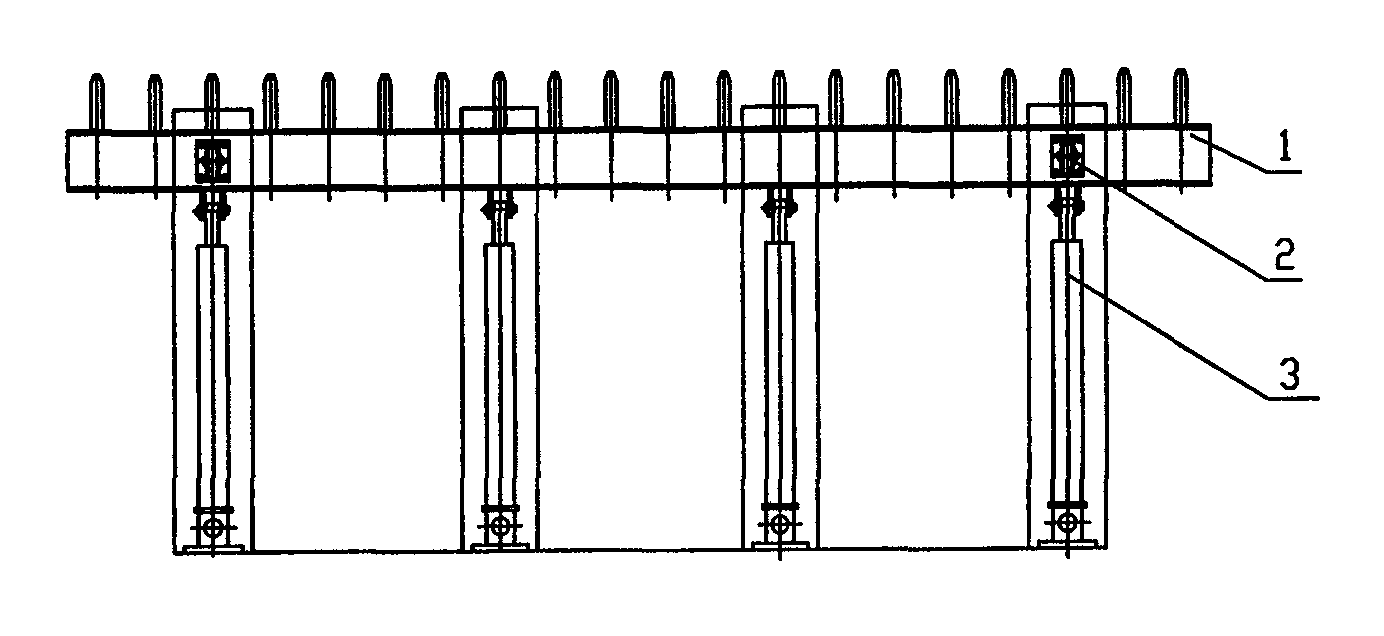
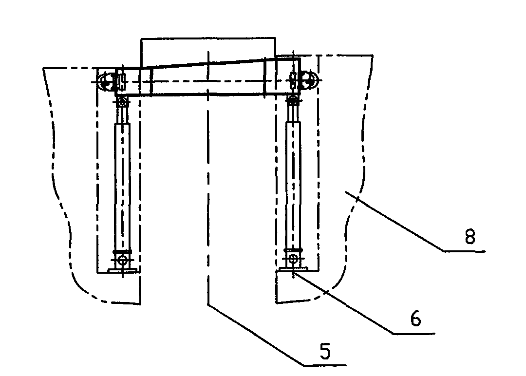
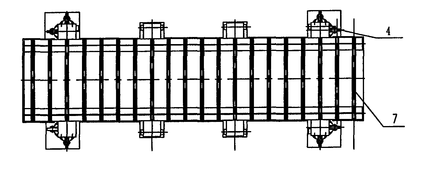
[0012] Such as figure 1 , figure 2 , image 3 As shown, a hydraulic cleaning machine for the grid dam at the bottom of a power station includes a movable grid support frame 1, a guide wheel positioning device 2, a hydraulic roof 3, a lateral pulley positioning 4, a corridor 5, a hydraulic roof support 6 and a fixed Bar 7, hydraulic jack 3 and lateral positioning wheel 4 are installed on the both sides of gallery 5, and hydraulic jack 3 is positioned on hydraulic jack support 6, and hydraulic jack support 6 is fixed on the concrete 8 of dam body, on the dam body Install the fixed grid 7 on the same plane as the top movable grid support frame 1, and fix the fixed grid 7 on the walls on both sides of the dam body, adjust the gap between the movable grid and the fixed grid, and install the guide wheel positioning device 2 on the movable The side of grid bar support frame 1 controls the left and right direction positioning of movable grid bar support frame 1, and the hydraulic s...


PUM


Abstract

The invention relates to a hydraulic trash remover for a bottom grid diversion dam of a power station, comprising a movable grid bar support frame, a guide wheel positioning device, a hydraulic jack, a lateral pulley positioning device, a corridor, a hydraulic jack supporting seat and fixed grid bars, wherein the hydraulic jack and a lateral positioning pulley are installed on both sides of the corridor, and the hydraulic jack is positioned on the hydraulic jack supporting seat fixed on concrete of a dam body; and the fixed grid bars are installed on the same plane of the movable grid bar support frame on the top of the dam body and are fixed on walls on both sides of the dam body, gaps between movable grid bars and the fixed grid bars installed are well adjusted, the guide wheel positioning device is installed on the lateral face of the movable grid bar support frame so as to ensure that the movable grid bar support frame can be leftwards and rightwards positioned, and a hydraulic system in a control room on the dam top is connected with hydraulic pipelines embedded in grooves on both sides of the dam body. As the structure is adopted, by controlling the hydraulic jack, the movable grid bar support frame is operated to move up and down to make reciprocating movement so that silt can be loosened, and the impulsive force of water is utilized for automatically carrying away the silt, thereby achieving the purposes of automatic trash removal and time and labor saving.

Description

technical field [0001] The invention relates to a semi-automatic cleaning machine for the bottom grid dam of a small and medium-sized power station, in particular to a hydraulic cleaning machine for the bottom grid dam of the power station. Background technique [0002] At present, the bottom barrier dam of the power station is commonly used to clean the sewage manually, which is labor-intensive and time-consuming. Moreover, it is impossible to clean the sewage manually when the flood comes. It can only be cleaned after the flood subsides, which wastes water resources. Can not get better economic benefits. Contents of the invention [0003] The object of the present invention is to provide a hydraulic cleaning machine for the barrier dam at the bottom of the power station, which adopts a full hydraulic control device to achieve the purpose of automatic cleaning and saves time and effort. [0004] The object of the present invention is achieved in this way: a hydraulic cle...

Claims


Application Information

Patent Timeline
Patent Type & Authority Applications(China)
IPC IPC(8): E02B8/02E02F5/32
Inventor 王明乾明兵袁兵乔华余祖红
Owner HUBEI XINGFA CHEM GRP CO LTD
Why Eureka
Try Eureka