Pivot device capable of being rightly assembled

A hinge, the correct technology, applied in the field of hinges, to achieve the effect of correct locking position and friction torque

Inactive Publication Date: 2011-05-18
JARLLYTEC CO LTD
View PDF4 Cites 1 Cited by
  • Summary
  • Abstract
  • Description
  • Claims
  • Application Information

AI Technical Summary

Problems solved by technology

[0003] However, the structural design of clamshell electronic devices is constantly changing, and the required locking position and cam components are becoming more and more complicated. In the case of misalignment, the fixing part and the sliding part of the cam member cannot be fastened, resulting in a wrong locking position and loss of proper frictional torque. Usually, the above situation can only be checked after the assembly is completed.

Method used


Image

  • Pivot device capable of being rightly assembled
  • Pivot device capable of being rightly assembled
  • Pivot device capable of being rightly assembled

Examples


Embodiment Construction

[0063] In order to further understand the features, technical means, and specific functions achieved by the present invention, more specific embodiments are listed hereafter, which will be described in detail in conjunction with the accompanying drawings.

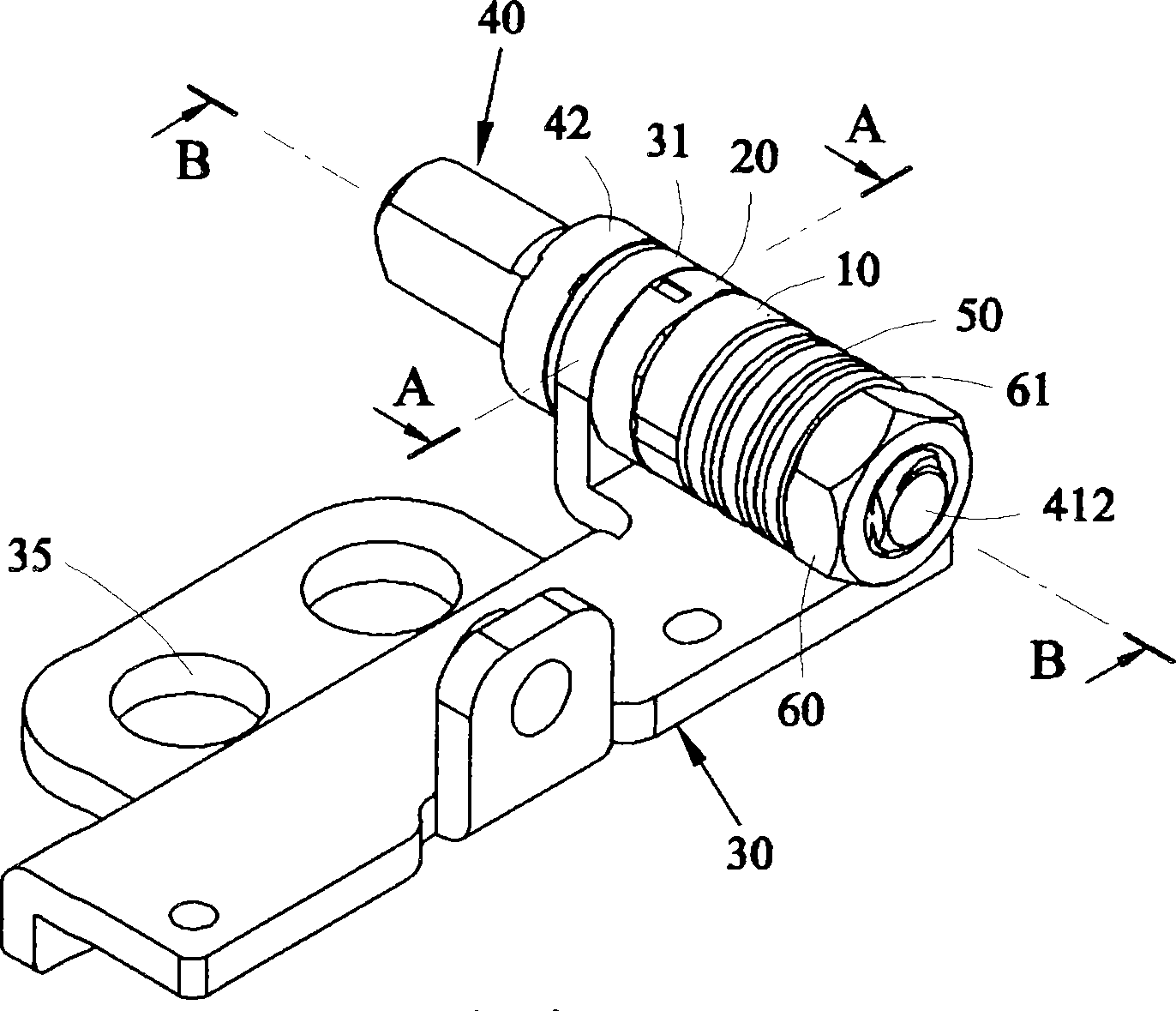
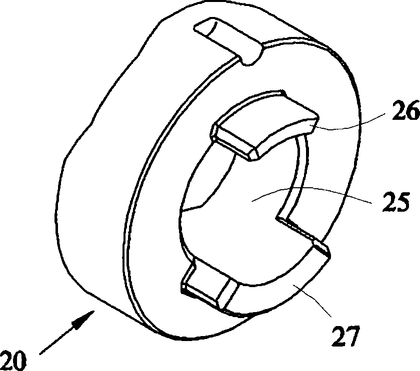
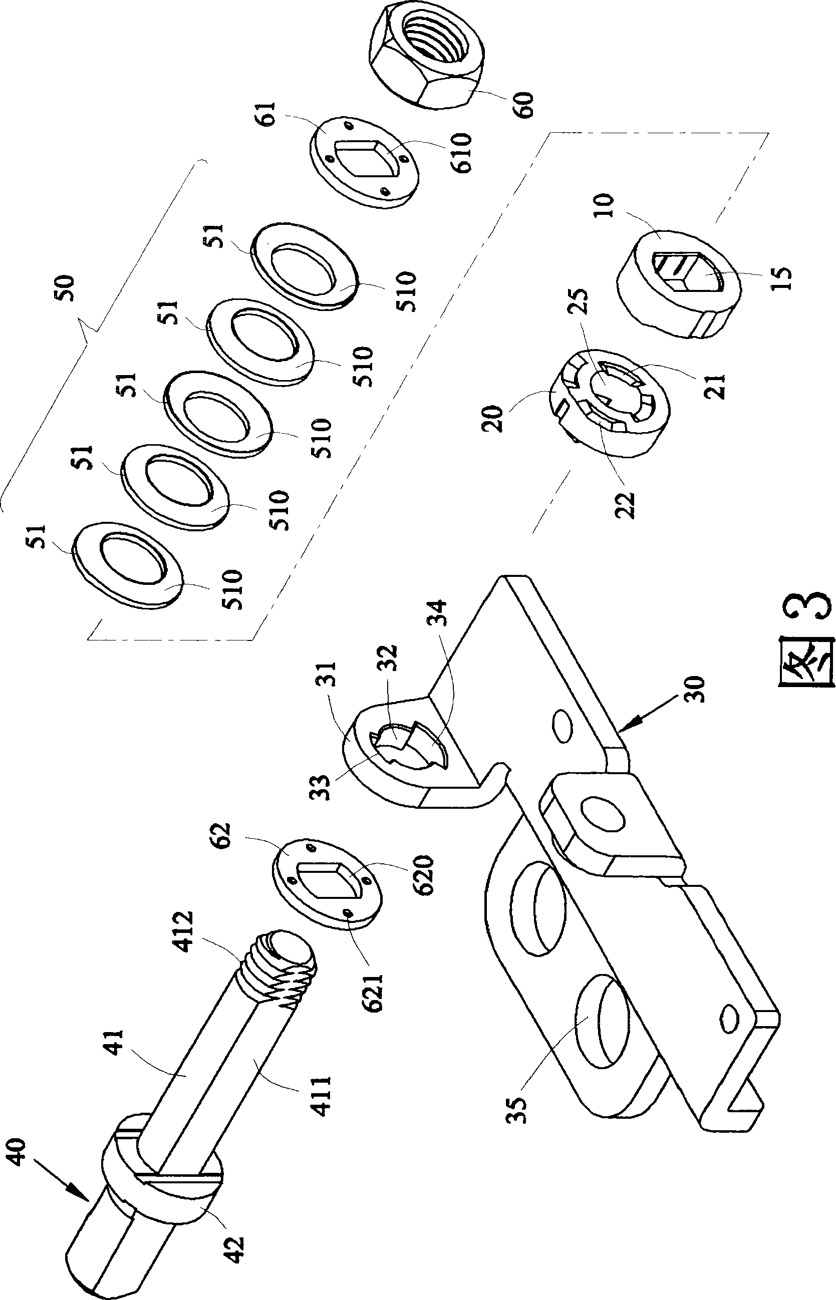
[0064] see figure 1 As shown in Figure 3, in a preferred embodiment, the hinge device of the present invention includes a first locking member 10, a second locking member 20, a pivot seat 30, a spindle 40 and an elastic assembly 50; the first locking member 10 One side is provided with an inner ring protrusion 11 and an outer ring protrusion 12; the second locking member 20 is provided with an inner ring groove 21 and an outer ring groove 22 on one side, and the second locking member 20 is provided with a The first positioning block 26 and the second positioning block 27; the pivot seat 30 is provided with a pivot hole 32 on the side plate 31, and the pivot hole 32 has a first positioning groove 33 and a second positioning...


PUM


Abstract

The invention relates to a pivot device capable of being rightly assembled. A second latching piece is provided with a first positioning block and a second positioning block, and pivot holes of a pivot seat are provided with a first positioning groove and a second positioning groove so that a first latching piece and the second latching piece can be rightly assembled with the pivot seat to reach a right latching position and friction torque force.

Description

technical field [0001] The invention relates to a hinge device that can be correctly assembled, especially a hinge device suitable for flip-top devices, and the hinge device is provided with first and second locking parts. Background technique [0002] The known technology such as the patent No. M297612 "effort-saving cam member" in Taiwan, China, owned by the applicant of this case and announced on September 11, 2006, is formed by docking a fixed part and a sliding part, and a Shaft hole and an embedding hole, two opposite ends of the periphery of the two components form a spiral slope respectively, so that the two ends have a vertex and an adjacent low point of height difference respectively; The apexes of the apexes resist each other, and when one of the components rotates, the two apexes move from the high point to the low point along the corresponding slope of the adjacent component. [0003] However, the current clamshell electronic devices are constantly seeking inn...

Claims


Application Information

Patent Timeline
Patent Type & Authority Patents(China)
IPC IPC(8): F16C11/10
Inventor 黄至忠李坤哗
Owner JARLLYTEC CO LTD
Why Eureka
Try Eureka