Tube core feeding and blanking mechanism

A technology of blanking mechanism and tube core, which is applied in the direction of conveyor objects, electrical components, semiconductor/solid-state device manufacturing, etc., and can solve problems such as difficulty in improving efficiency, small tube core shape, and mechanical inability to realize flow operation, etc.

Inactive Publication Date: 2009-12-16
冯建新
View PDF0 Cites 1 Cited by
  • Summary
  • Abstract
  • Description
  • Claims
  • Application Information

AI Technical Summary

Problems solved by technology

[0002] The operation of the tube core, pole plate and solder glue of the silicon rectifier bridge of the automobile generator, due to the uncertain position of the multi-station of the pole plate and the small shape of the tube core,

Method used


Image

  • Tube core feeding and blanking mechanism

Examples


Embodiment Construction

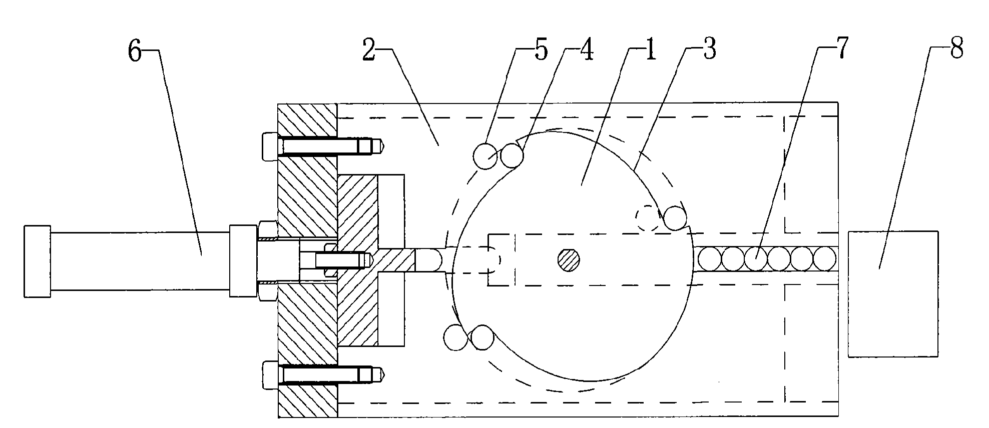
[0011] Such as figure 1 As shown, the die loading and blanking mechanism of the present invention includes a distribution plate 1 and a blanking plate 2, the distribution plate 1 is circular, and a plurality of arc grooves 3 are arranged on the circumference, and the arc The bottom of the groove 3 is provided with a die clamping position 4; the blanking tray 2 is located at the bottom of the distribution plate 1, and a plurality of blanking holes 5 are provided on the blanking disc 2 corresponding to the die clamping position 4. The disc 2 is driven by the cylinder 6 to perform lateral telescopic movement, and the distribution disc 1 is driven by a stepping motor.

[0012] The stepping motor drives the distribution plate 1 to run, and the dies 7 are loosened to the distribution plate 1 by the feeder 8 along the slideway, and enter the position of the die clamping position 4 of the arc groove 3 one by one. When the stepper motor completes a cycle, the cylinder 6 drives the bla...


PUM


Abstract

The invention discloses a tube core feeding and blanking mechanism comprising a distribution plate and a blanking plate, wherein the distribution plate is round and is provided with a plurality of arc-shaped grooves on the circumference, and the bottoms of the arc-shaped grooves are provided with tube core blocking positions; the blanking plate is arranged at the lower part of the distribution plate and provided with a plurality of blanking holes corresponding to the tube core blocking positions; the blanking plate is driven by an air cylinder to do transverse concertina movement; and the distribution plate is driven by a stepping motor. The mechanism is suitable for the tube core feeding and assembling of an automatic welding machine of a silicon rectifier crossover tube core of an automobile power generator, and can substitute the laggard production mode of manually assembling ever since a long time ago, ensure the multi-position, high precise and synchronous tube core feeding and assembling, improve the working efficiency and lower the labor cost.

Description

technical field [0001] The invention relates to the field of semiconductor packaging, in particular to a tube core feeding and blanking mechanism applied to an automatic welding machine for silicon rectifier bridge tube cores of automobile engines. Background technique [0002] The operation of the tube core, pole plate and solder glue of the silicon rectifier bridge of the automobile generator, due to the uncertain position of the multi-station of the pole plate and the small shape of the tube core, ordinary machinery cannot realize flow operation, and can only be done by Workers operate manually. And people's manual operation generally requires higher technical proficiency of workers, and the efficiency is difficult to improve. Therefore, based on the above-mentioned problems, I designed an automatic welding machine, realized a large number of tube core assembly, and increased labor productivity by 3-5 times, saving more than half of labor costs. The present invention is ...

Claims


Application Information

Patent Timeline
IPC IPC(8): H01L21/677H01L21/60
Inventor 冯建新
Owner 冯建新
Why Eureka
Try Eureka