
Condition dependent sharpening in an imaging device

A technology of imaging equipment and conditions, applied in image enhancement, image analysis, electrical components, etc., can solve the problems of infeasible, high cost, and unsuitable optomechanical solutions

Inactive Publication Date: 2009-12-16
EASTMAN KODAK CO
View PDF0 Cites 1 Cited by
  • Summary
  • Abstract
  • Description
  • Claims
  • Application Information

AI Technical Summary

Problems solved by technology

Unfortunately, due to these limited options, solutions are often physically large and unsuitable for size-constrained systems such as small cameras
Furthermore, optomechanical solutions are not feasible in inexpensive imaging devices due to high cost

Method used

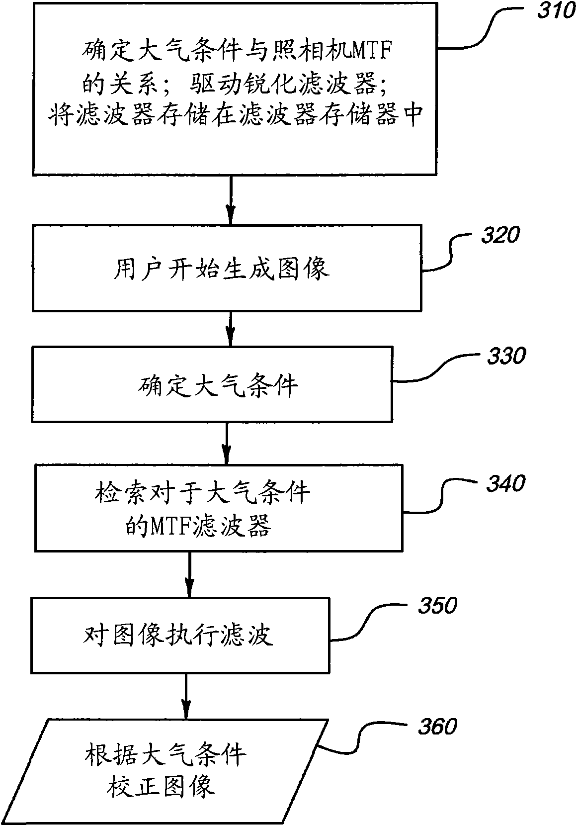
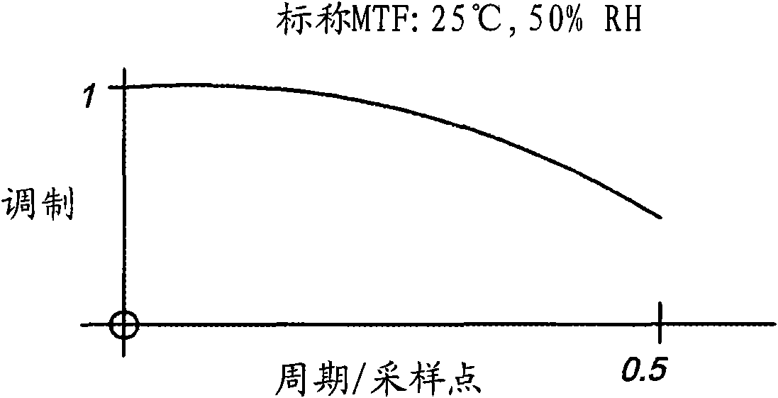

Image

  • Condition dependent sharpening in an imaging device
  • Condition dependent sharpening in an imaging device
  • Condition dependent sharpening in an imaging device

Examples


Embodiment Construction

[0016] The invention will be described with reference to illustrative embodiments. It is anticipated that many modifications may be made to these examples and still result within the scope of the invention. No limitation with respect to the particular embodiments described herein is intended or should be inferred.

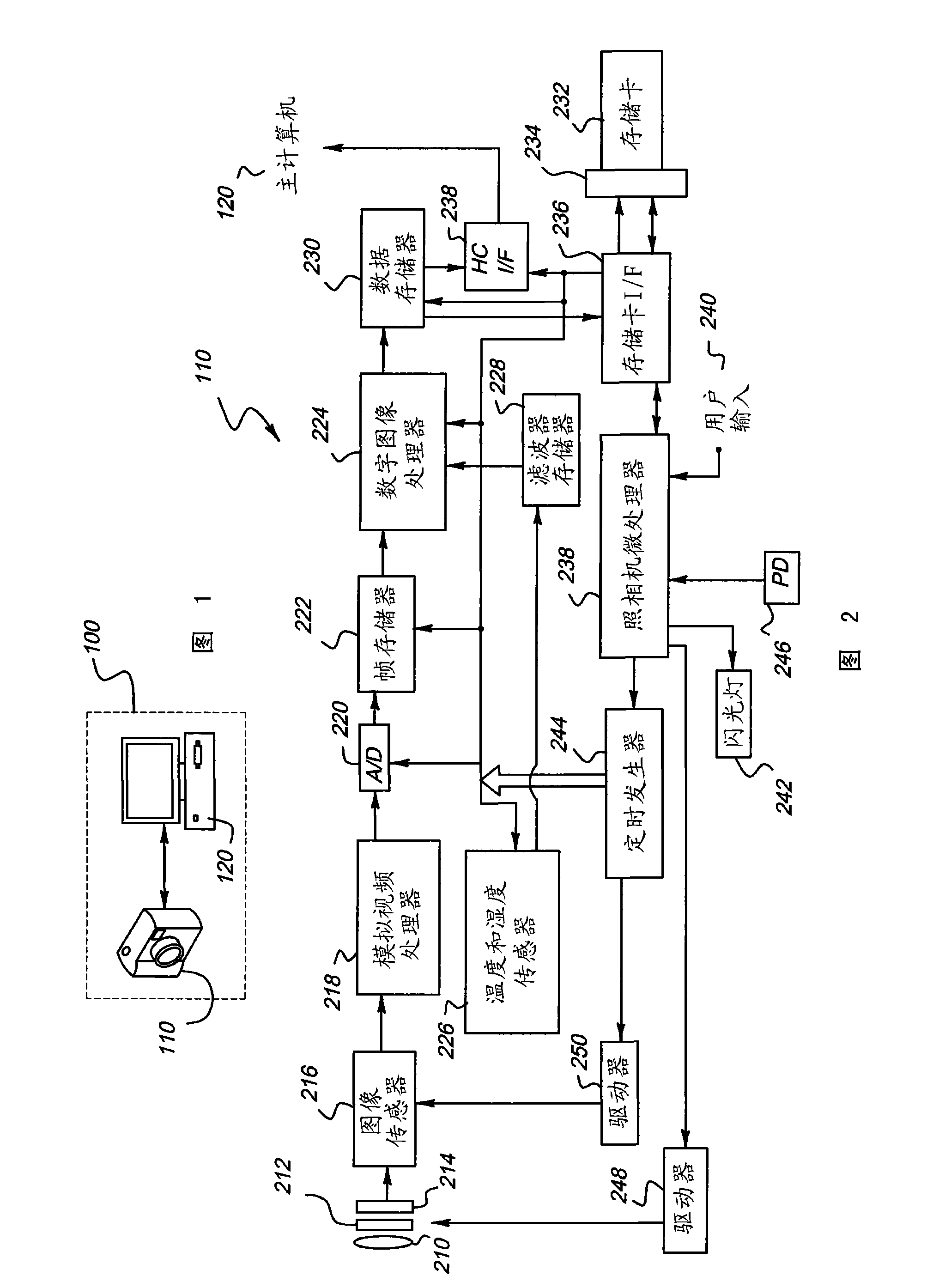
[0017] figure 1 A block diagram of an illustrative digital imaging system 100 in which aspects of the invention may be implemented is shown. This particular digital imaging system includes a digital camera 110 and a computer 120 . However, some other configurations are conceivable and fall within the scope of the invention. Imaging systems include not only digital cameras, but may also include, for example, film cameras having optical scanners operable to convert images developed on film into digital data. Alternatively, the imaging system may include a video camera instead of a still camera. A digital camera can be combined with another device such as a mobil...


PUM


Abstract

Blur is reduced in an image generated by an imaging device by determining values of one or more atmospheric variables for the image, the one or more atmospheric variables characterizing conditions under which the image is generated. With these values, a sharpening filter is determined for the image. The sharpening filter is derived from a modulation transfer function of the imaging device at conditions characterized by the values of the one or more atmospheric variables determined for the image. The sharpening filter is subsequently applied to the image.

Description

technical field [0001] The present invention relates generally to digital imaging devices, and more particularly to reducing defocus blur in images caused by atmospheric conditions. Background technique [0002] Temperature and humidity fluctuations that act on optical components in an imaging device can cause changes in the optical properties of the optical components, thereby adversely affecting the performance of the imaging device. Changes in temperature and humidity, for example, can cause optical components to change their refractive index, change shape, and move within their holders. These manifestations are especially prevalent in imaging devices that include plastic optics. Plastic optics, such as those found in inexpensive cameras, often have a refractive index that varies to a greater extent as a function of atmospheric conditions than does the refractive index of glass optics. As a result, plastic optics may not maintain focus over the wide temperature and humi...

Claims


Application Information

Patent Timeline
Patent Type & Authority Applications(China)
IPC IPC(8): G06T5/00
CPCG06T2207/20004H04N2201/3278H04N2101/00H04N2201/3277H04N2201/3225G06T5/001H04N5/217G06T5/003H04N23/81G06T5/00G06T1/00
Inventor S·C·凯利S·C·卡哈尔
Owner EASTMAN KODAK CO
Learn More