Twisting method of ultra-fine nylon stretch yarn and device thereof

A twisting device and elastic yarn technology, applied in textiles, papermaking, yarn, etc., can solve the problems of reducing the quality of nylon elastic yarn products, increasing the number of feeding bobbins, increasing twisted yarn knots, etc., to achieve uniform twist Good rate and quality, low energy consumption, and improved twisting efficiency

Inactive Publication Date: 2009-12-23
绍兴华裕纺机有限公司
View PDF0 Cites 4 Cited by
  • Summary
  • Abstract
  • Description
  • Claims
  • Application Information

AI Technical Summary

Problems solved by technology

[0004] However, there are also some disadvantages in twisting ultra-fine nylon elastic yarns with covered silk spindles: 1. Since the twisting of covered silk spindles is single twist, that is, only one twist is added to nylon elastic yarns after one turn of the spindle. low twist efficiency
Reducing the weight of the feeding bobbin means reducing the amount of silk in the feeding bobbin, which will increase the number of doffing times of the feeding bobbin, increase the knot of the twisted yarn, and reduce the quality of the nylon elastic yarn product

Method used


Image

  • Twisting method of ultra-fine nylon stretch yarn and device thereof
  • Twisting method of ultra-fine nylon stretch yarn and device thereof
  • Twisting method of ultra-fine nylon stretch yarn and device thereof

Examples


Embodiment 1

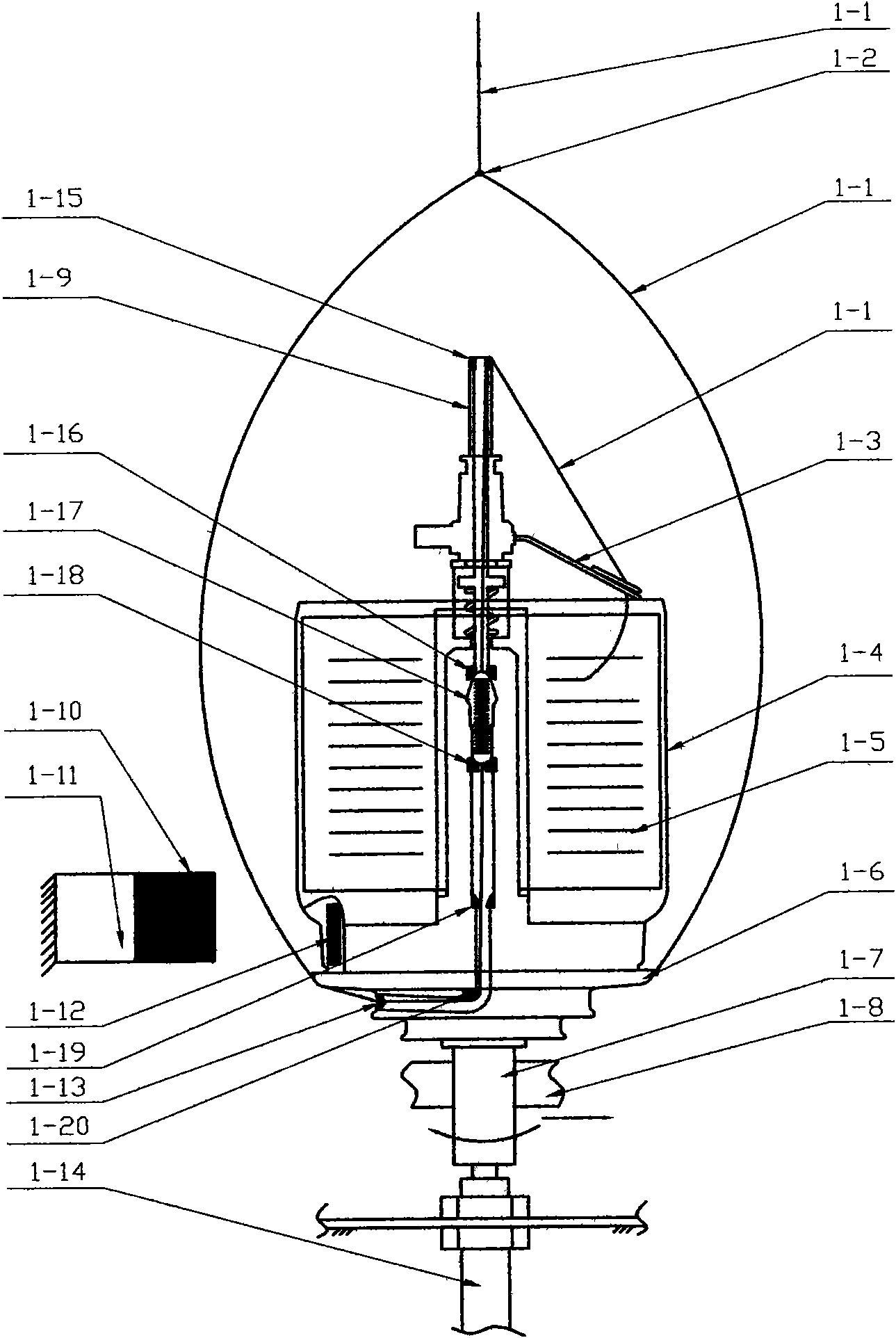
[0029] Such as figure 2 As shown, the spindle disk 1-7 is fixed on the fuselage through the spindle base 1-14, the twist disk 1-6 is connected with the spindle disk 1-7, and the yarn pot 1-4 passes through the bearing transition and is installed on the twist disk 1-6. Above, there is no bending porcelain part 1-20 at the middle horizontal hole of the twist disc 1-6, and the outlet of the outer end of the horizontal hole is provided with a wire outlet porcelain part 1-13, and the outer magnet 1-10 is installed in the outer magnetic disk 1-11, The outer magnetic disk 1-11 is fixed on the fuselage; the inner magnet 1-12 is contained in the yarn pot 1-4, and attracts each other with the outer magnet 1-10 to generate a magnetic positioning effect, so that the yarn pot 1-4 is stationary. The feeding bobbin 1-5 is installed in the yarn pot 1-4, the silk thread 1-1 is wound on the feeding bobbin 1-5, the flyer 1-3 is installed on the tension tube 1-9, and on the tension tube 1-9 Amo...

Embodiment 2

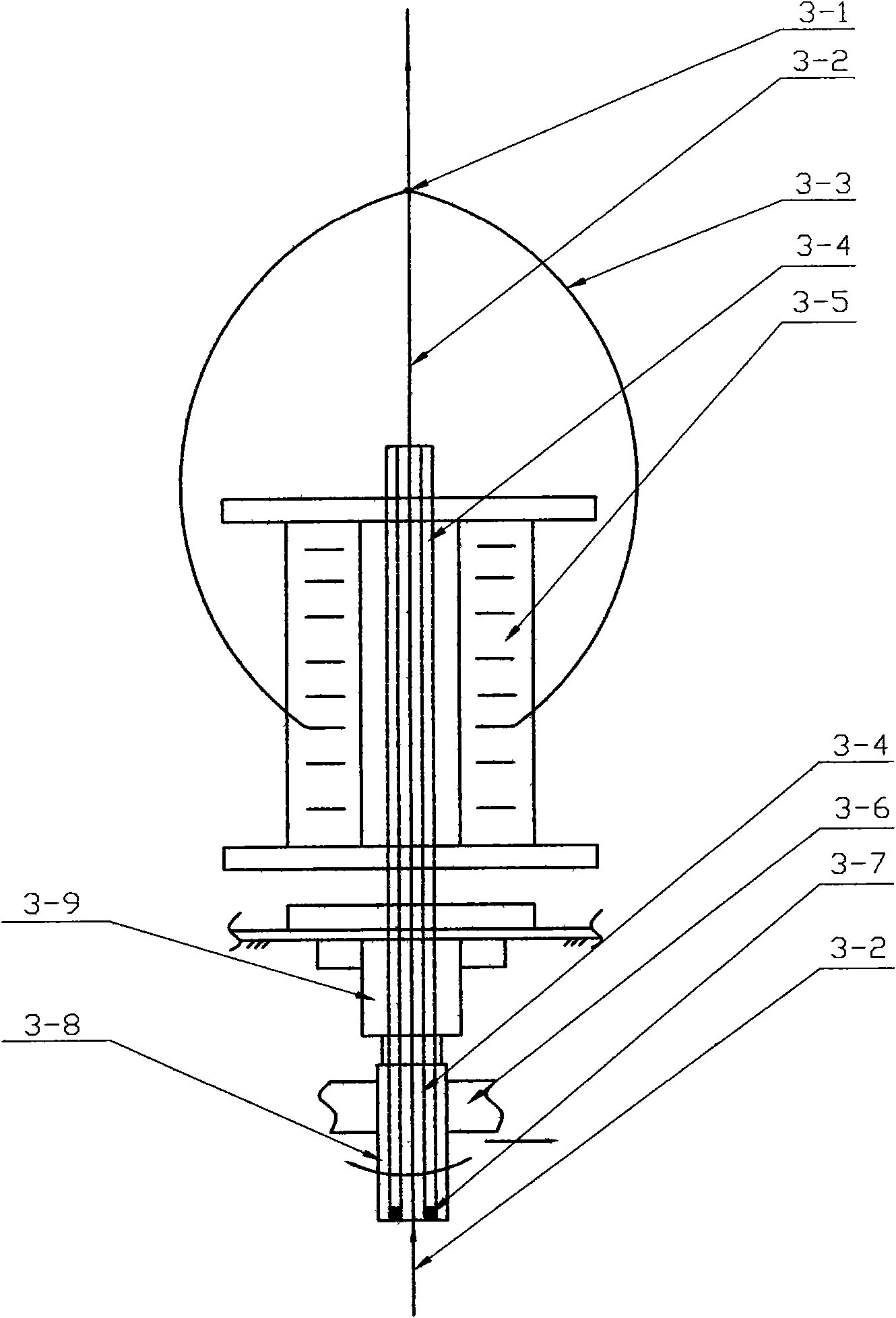
[0032] like image 3 As shown, the spindle disc 2-7 is fixed on the machine body through the spindle seat 2-14, the rotor cup 2-6 is connected with the spindle disc 2-7, and the stationary cup 2-4 passes through the bearing transition and is installed on the rotor cup 2-6. Inside, the middle horizontal hole of the rotor cup 2-6 is provided with a bending ceramic piece 2-18, and the outlet of the outer end of the horizontal hole is provided with a wire outlet ceramic piece 2-13, and the outer magnet 2-10 is installed in the outer disk 2-11 , the outer magnetic disk 2-11 is fixed on the fuselage; the inner magnet 2-12 is installed in the stationary cup 2-4, and attracts each other with the outer magnet 2-10 to generate a magnetic positioning effect, so that the stationary cup 2-4 is stationary . The feeding bobbin 2-5 is installed in the static cup 2-4, the silk thread 2-1 is wound on the feeding bobbin 2-5, the guide wire cap 2-3 is installed on the tension tube 2-9, and on th...


PUM


Abstract

The invention discloses a twisting method of ultra-fine nylon stretch yarn and a device thereof, belonging to the technical field of textile. The invention utilizes a doubler winder with polyurethane fibre drawing to process the two-for-one twisting feeding tube of the ultra-fine nylon stretch yarn, and then utilizes a two-for-one twister spindle to twist the ultra-fine nylon stretch yarn. The invention utilizes one bout plus two turns of a two-for-one twisting spindle, which has the advantages of constant air ring, constant tension and big package, so that the twisting method of the invention improves production efficiency, effectively realizes myriametre knot-free yarn, improves the equality index of thrown silk degree of twist, and lowers energy consumption of yield per unit. The invention provides a new method and technical device for producing ultra-fine nylon stretch yarn with high efficiency, good quality and small energy consumption.

Description

technical field [0001] The invention relates to a twisting method and device for superfine nylon elastic yarn, belonging to the technical field of textile machinery. Background technique [0002] Ultra-fine nylon elastic yarn is often used in hosiery, elastic underwear, underwear and other fabrics. It is usually drawn with 12D----75D nylon low-elasticity yarn and 20D----40D spandex yarn at a ratio of about 1:3. It is made by twisting and plying. The traditional twisting method of ultra-fine nylon elastic yarn is to use a special winding machine to wind the processed nylon yarn on the sided bobbin dedicated to the covering yarn machine, and then use the covering yarn spindle to twist the nylon yarn and spandex yarn. After drawing, it is paralleled and twisted. The specific structure is as figure 1 As shown, the belt pulley 3-8 equipped with the hollow spindle bar 3-4 is installed on the spindle base 3-9 through the bearing transition, and the spindle base 3-9 is installed ...

Claims


Application Information

Patent Timeline
Patent Type & Authority Applications(China)
IPC IPC(8): D02G3/32D02G3/04D01H7/86D01H7/04
Inventor 刘光容
Owner 绍兴华裕纺机有限公司
Why Eureka
Try Eureka