Method for clinching thick metal workpieces, use of a clinching tool, and steel structural element produced accordingly

A technology for metal workpieces and steel structural parts, which is used for riveting thick metal workpieces, can solve the problems of inability to rivete metal plates and other metal workpieces, and achieve the effects of less joint cost, avoidance of distortion, and good support characteristics.

Inactive Publication Date: 2009-12-23
FRAUNHOFER GESELLSCHAFT ZUR FOERDERUNG DER ANGEWANDTEN FORSCHUNG EV
View PDF9 Cites 13 Cited by
  • Summary
  • Abstract
  • Description
  • Claims
  • Application Information

AI Technical Summary

Problems solved by technology

[0008] However, so far it has not been possible to rivet metal plates and other metal workpieces with a thickness greater than 4mm.
Furthermore, until now it was only possible to join two identical or similar metal sheets to each other by riveting

Method used


Image

  • Method for clinching thick metal workpieces, use of a clinching tool, and steel structural element produced accordingly
  • Method for clinching thick metal workpieces, use of a clinching tool, and steel structural element produced accordingly
  • Method for clinching thick metal workpieces, use of a clinching tool, and steel structural element produced accordingly

Examples


Embodiment Construction

[0045] As stated at the beginning of the description, the scope of the present application relates to riveting without cutouts. The form of riveting is a pure deformation joining process. The joining of the workpieces takes place exclusively by means of osmotic bonding sinking and subsequent compression. The basic idea behind the development of this method without cutting parts is firstly to seek an increase in the hardness of the connection caused by greater material cohesion.

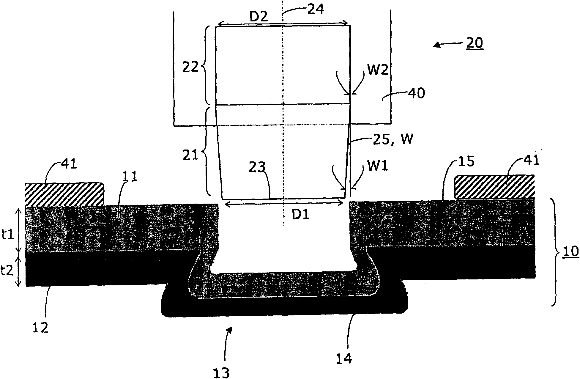
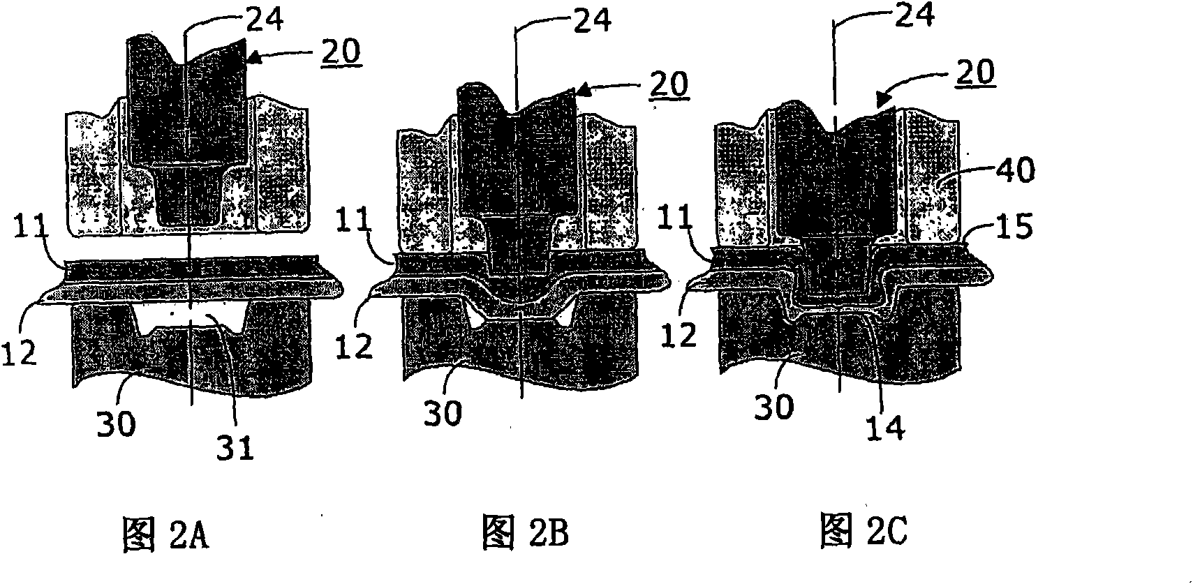
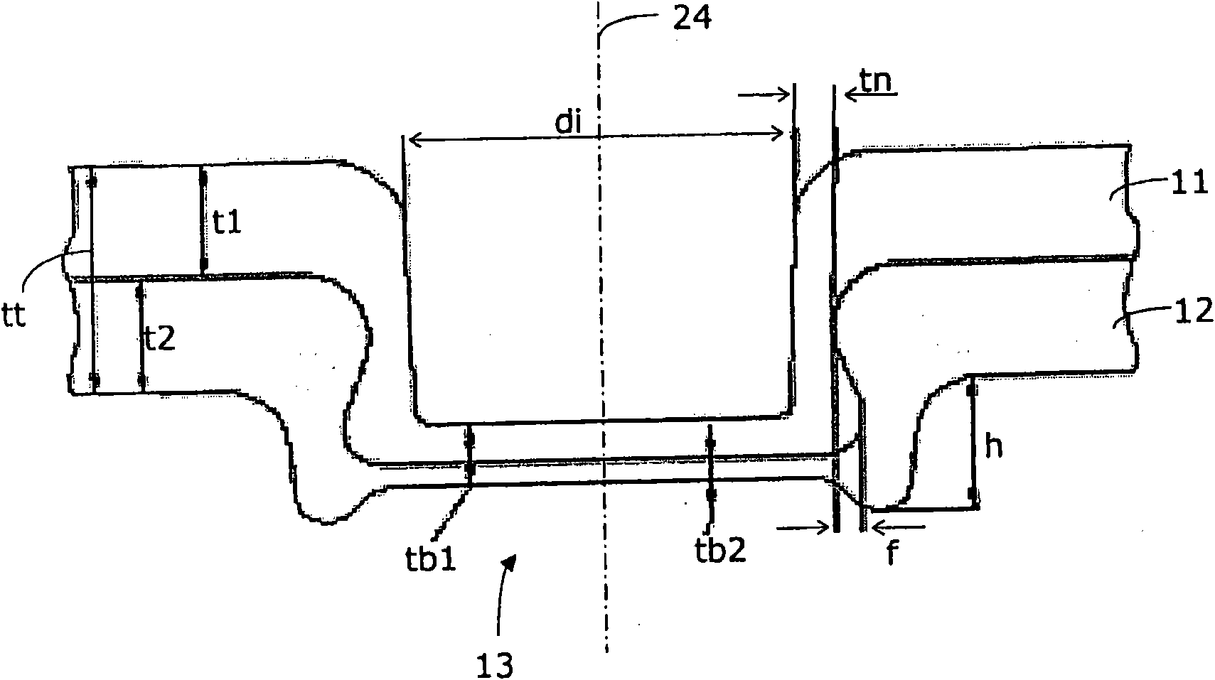
[0046] exist figure 1 The principle of the invention is only schematically shown in the diagram. The two metal workpieces 11 and 12 shown are connected to one another by means of riveting 13 . A part of the punch 20 , referred to here as the punch, is shown above the rivet 10 or the rivet point 10 .

[0047] The riveting tool 20 comprises a punch and a collapsing tool 30 which can be designed as a die or an anvil. The punch is designed rotationally symmetrically with respect to its axis of rotati...


PUM

PropertyMeasurementUnit
thicknessaaaaaaaaaa
diameteraaaaaaaaaa

Abstract

The invention relates to a method for the production of a load-bearing structural steel connection, wherein a clinching connection (13) is formed by means of a male die (20) and a female die (30) using local deformation, the connection connecting a first metal workpiece (6.1, 6.2) to a second metal workpiece (6.3, 6.4). For this purpose, the first metal workpiece (6.1, 6.2) and the second metal workpiece (6.3, 6.4) are first placed on top of each other on a processing surface of the female die and aligned. Subsequently the die of the male die is applied and lowered into the two metal workpieces (6.1, 6.2; 6.3, 6.4) placed on top of each other until the clinching connection (13) has been formed by plastic deformation. The first metal workpiece (6.1, 6.2) has a first workpiece thickness (tl), and the second metal workpiece (6.3, 6.4) has a second workpiece thickness (t2) that together result in a total workpiece thickness (tt), which is greater than 8 mm. The die is configured in a rotationally symmetrical manner with regard to the rotational axis (24) thereof and has a conically shaped transitional region (21, 22) tapering at an angle (W, W1, W2) in the lowering direction of the die.

Description

technical field [0001] The invention relates to a method for riveting thick metal workpieces according to the preamble of claim 1 for producing load-bearing riveted parts, corresponding riveting in steel structures according to the preamble of claim 9 The method of use of the parts, and the correspondingly manufactured steel structural parts according to the preamble of claim 13, especially steel structural parts used in escalators or moving walkways or elevator installations. Background technique [0002] Riveting has long been known as a deformation joining method. This method is also known as crimping. Riveting is a transformational joining process which, depending on the embodiment, does not require the use of auxiliary joining elements. [0003] For riveting there are various variants for producing joints. The characteristics of riveting are as follows: [0004] - according to the structure of the joined elements: riveting with cut parts and riveting without cut par...

Claims


Application Information

Patent Timeline
Patent Type & Authority Applications(China)
IPC IPC(8): B21D39/03B21J15/02F16B5/04
CPCB21D39/031F16B5/045B66B23/00Y10T403/49Y10T29/53709Y10T403/4991Y10T29/49924Y10T29/49943Y10T403/4966Y10T29/49915Y10T29/49936Y10T403/4949Y10T29/49623B21D39/03B21J15/02F16B5/04
Inventor A·特洛杰D·克拉姆佩尔M·马泰塞尔R·舒茨T·诺瓦塞克
Owner FRAUNHOFER GESELLSCHAFT ZUR FOERDERUNG DER ANGEWANDTEN FORSCHUNG EV
Why Eureka
Try Eureka