Manufacturing method of dustproof unit

A manufacturing method and a dust-proof technology, which are applied in the fields of pollution prevention methods, chemical instruments and methods, cleaning methods and utensils, etc., can solve the problems of uneven force, increased material cost, deformation and damage, etc., to improve dust-proof performance. effect, avoid assembly tolerances, reduce the effect of deformation damage

Active Publication Date: 2009-12-30
TBI MOTION TECH CO LTD
View PDF0 Cites 8 Cited by
  • Summary
  • Abstract
  • Description
  • Claims
  • Application Information

AI Technical Summary

Problems solved by technology

[0005] However, the track dustproof component 121 and the end cover dustproof component 131 are manufactured separately, therefore, the joints of the two often produce unavoidable assembly tolerances, and then the dustproof component 121 and the end cover dustproof component 131 are completely separated. Decreased effect
Moreover, when the assembly tolerance of the track dustproof element 121 and the end cover dustproof element 131 is too large, the track dustproof element 121 is more likely to be deformed and damaged due to uneven force when the ball nut 12 and the track body 11 move relative to each other. It must be replaced, which also results in an increase in the cost of materials

Method used


Image

  • Manufacturing method of dustproof unit
  • Manufacturing method of dustproof unit
  • Manufacturing method of dustproof unit

Examples


Embodiment Construction

[0034] The method of manufacturing the dust-proof unit according to the preferred embodiment of the present invention will be described below with reference to the relevant drawings.

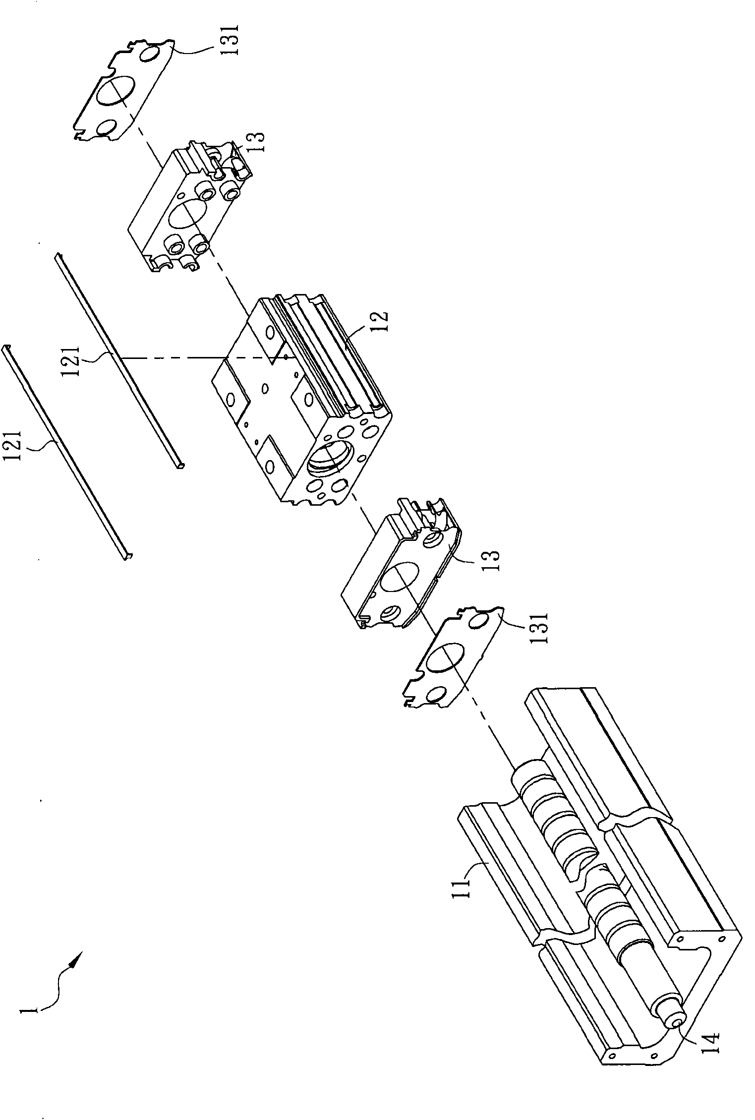
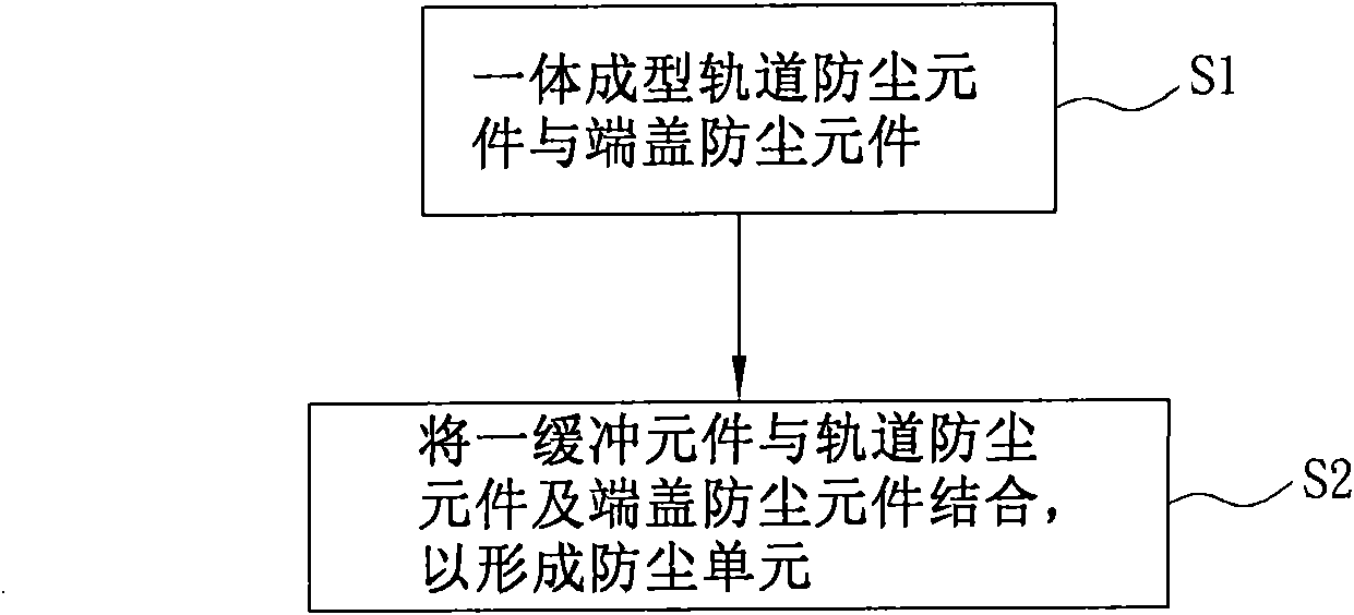
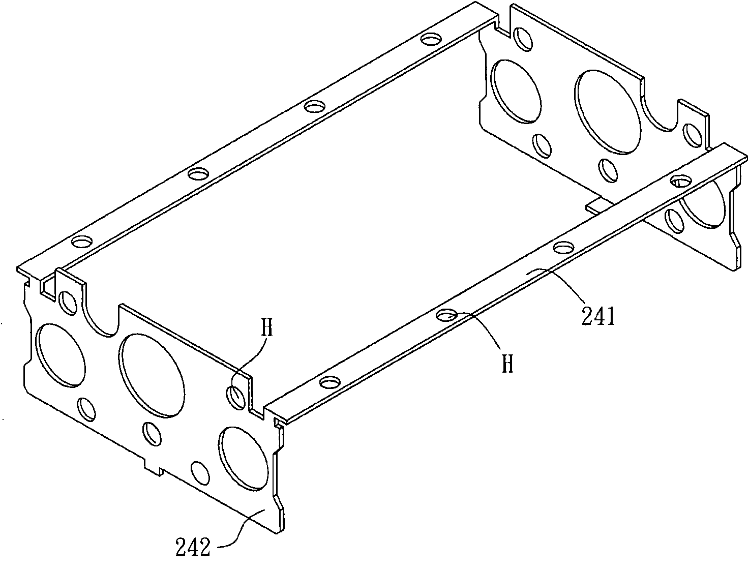
[0035] Please refer to figure 2 As shown, a method of manufacturing a dustproof unit of the present invention includes step S1 and step S2. Please refer to figure 2 and Figure 3A As shown, step S1 integrally forms the track dust-proof component 241 and the end cover dust-proof component 242 . In this embodiment, the two track dustproof components 241 and the two end cover dustproof components 242 are taken as examples for illustration. Wherein, the one-piece molding method, for example, uses the same mold to form the track dustproof component 241 and the end cover dustproof component 242, and then processes and bends the track dustproof component 241 and the end cover dustproof component 242, etc., but it is not limited.

[0036] The track dustproof element 241 and the end cap dustproof e...


PUM


Abstract

The invention relates to a manufacturing method of a dustproof unit. The dustproof unit is used for a linear motion device and provided with a track dustproof element and an end cover dustproof element, wherein the track dustproof element is connected with a rolling ball nut cap of the linear motion device, and the end cover dustproof element is connected with an end cover of the linear motion device. The manufacturing method comprises the following steps: integrally molding the track dustproof element and the end cover dustproof element; and combining a buffering element with the track dustproof element and the end cover dustproof element so as to form the dustproof unit.

Description

technical field [0001] The invention relates to a manufacturing method of a dustproof unit. Background technique [0002] In order to make various working machines operate normally, the transmission device plays an important role. In the current technology, linear motion devices are often used as transmission devices for various working machines. [0003] Please refer to figure 1 As shown, a known linear motion device 1 includes a track body 11 , a ball nut 12 , two end caps 13 and a screw 14 . Wherein, the ball nut 12 , the end cap 13 and the screw rod 14 are arranged in the rail body 11 , the end cap 13 is fixed on both sides of the ball nut 12 , and the screw rod 14 passes through the ball nut 12 and the end cap 13 in sequence. [0004] When the ball nut 12 moves linearly along the track body 11, the end cover dustproof element 131 fixed on the end cover 13 can be used to scrape off debris or dust contaminated on the track body 11, and the The track dustproof element ...

Claims


Application Information

Patent Timeline
Patent Type & Authority Applications(China)
IPC IPC(8): B08B17/02F16H25/22
Inventor 李进胜杨进财
Owner TBI MOTION TECH CO LTD
Why Eureka
Try Eureka