Magnetic drive pump

A magnetic pump and magnetic drive technology, applied in the direction of pumps, pump devices, pump components, etc., can solve the problems such as the connection part is not corroded, reverse rotation, internal magnetic rotor or pump shaft damage, etc., to save maintenance costs, disassembly, etc. Simple process and cost saving effect

Inactive Publication Date: 2009-12-30
蔡国华
View PDF0 Cites 7 Cited by
  • Summary
  • Abstract
  • Description
  • Claims
  • Application Information

AI Technical Summary

Problems solved by technology

[0003] In the prior art, the inner magnetic rotor of the magnetic pump is often screwed to the pump shaft, but the disadvantage of this connection is that the pump shaft sometimes rotates in the opposite direction during the operation of the magnetic pump, which will cause the inner magnetic rotor to be in contact with the pump shaft. The pump shaft is separated, which leads to failure; therefore, nut connection is often used. In order to prevent liquid erosion, the nut is sealed with glue. However, when the inner magnetic rotor needs to be disassembled for maintenance, it is necessary to Cause damage to the inner magnetic rotor or pump shaft, so the existing magnetic pump cannot solve the problem of easy disassembly and no corrosion of the connection part

Method used


Image

  • Magnetic drive pump
  • Magnetic drive pump
  • Magnetic drive pump

Examples


Embodiment Construction

[0018] The present invention will be further described below in conjunction with the accompanying drawings and embodiments.

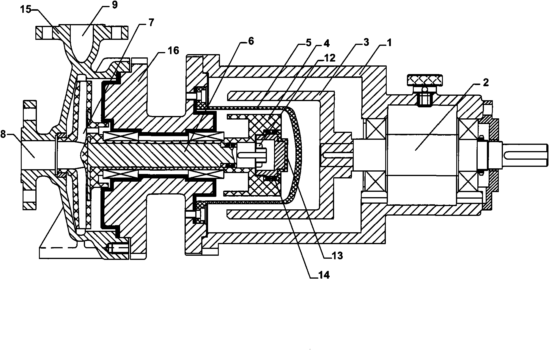
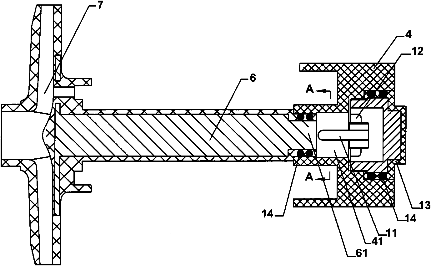
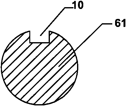
[0019] See attached figure 1 To attach image 3 , a magnetic pump, comprising a bracket 1, a transmission shaft 2 rotatably arranged inside the bracket 1, an outer magnetic rotor 3 fixedly arranged on the transmission shaft 2, concentrically arranged inside the outer magnetic rotor 3 and magnetically driven by the outer magnetic rotor 3 The inner magnetic rotor 4 rotating synchronously, the spacer 5 arranged between the outer magnetic rotor 3 and the inner magnetic rotor, the pump shaft 6 connected to the inner magnetic rotor 4 at one end, the impeller 7 connected to the other end of the pump shaft 6, The middle body 16 arranged outside the pump shaft 6 and fixedly connected with the bracket 1, the pump casing 15 arranged outside the impeller 7 and fixedly connected with the middle body 16, the liquid inlet 8 and the Liquid outlet 9, wherein the inner...


PUM


Abstract

The invention discloses a magnetic drive pump. The magnetic drive pump comprises a support, a drive shaft which is rotatably arranged in the support, a magnetic outer rotor which is fixedly disposed on the drive shaft, a magnetic inner rotor which is coaxially disposed in the magnetic outer rotor and driven by a magnetic force of the magnetic outer rotor for simultaneous rotation, a spacer sleeve which is arranged between the magnetic outer rotor and the magnetic inner rotor, a pump shaft one end of which is connected with the magnetic inner rotor, an impeller which is connected with the other end of the pump shaft, a midbody which is arranged outside the pump shaft and fixedly connected with the support, a pump shell which is arranged outside the impeller and fixedly connected with the midbody, a liquid inlet and a liquid outlet which are opened on the pump shell respectively, and the magnetic inner rotor is detachably connected with the pump shaft. The invention solves the problems of the prior art, and provides a magnetic drive pump with simple disassembly procedures.

Description

technical field [0001] The invention relates to a magnetic pump. Background technique [0002] The magnetic pump is a pump body driven by magnetic field force. It is mainly composed of three parts: pump head, magnetic drive device and other parts. The pump head part is mainly composed of impeller, pump body, bearing, shaft sleeve, pump cover, pump shaft and other parts; the magnetic drive part is mainly composed of inner magnetic rotor, outer magnetic rotor, spacer sleeve and other parts; other parts mainly include Brackets, bases, motors, intermediate bearing bodies and couplings, etc. A cylindrical outer magnetic rotor is installed on the motor shaft, and outer magnetic steel (permanent magnets) with N and S poles arranged alternately are evenly arranged on the inner cylindrical surface, and a cylindrical outer magnetic rotor (permanent magnet) is also installed on one end of the pump shaft. The inner magnetic rotor of the new type has inner magnetic steel (permanent mag...

Claims


Application Information

Patent Timeline
Patent Type & Authority Applications(China)
IPC IPC(8): F04D13/02F04D29/08F04D29/02
Inventor 蔡国华
Owner 蔡国华
Why Eureka
Try Eureka