
Oil hydraulic cylinder for braking

A technology of hydraulic cylinders and brakes, applied in the direction of brake actuators, etc., can solve the problems of rising processing and assembly costs, lower product competitiveness, deadlocks, etc., to achieve easy manufacturing and assembly, enhance competitiveness, and simplify components Effect

Inactive Publication Date: 2009-12-30
ASHIMA LTD
View PDF0 Cites 1 Cited by
  • Summary
  • Abstract
  • Description
  • Claims
  • Application Information

AI Technical Summary

Problems solved by technology

However, the existing structure has the problem of excessive braking force. When braking in an emergency, it may cause rollover or wheel deadlock due to excessive braking force, thus causing the rider to lose control and be injured.
[0003] Other existing structures that can prevent deadlock have complex structures and many components, which lead to increased processing and assembly costs and lower product competitiveness
[0004] Existing hydraulic cylinders for braking cannot distinguish different stages of deceleration or emergency braking and use different braking forces

Method used


Image

  • Oil hydraulic cylinder for braking
  • Oil hydraulic cylinder for braking
  • Oil hydraulic cylinder for braking

Examples


Embodiment Construction

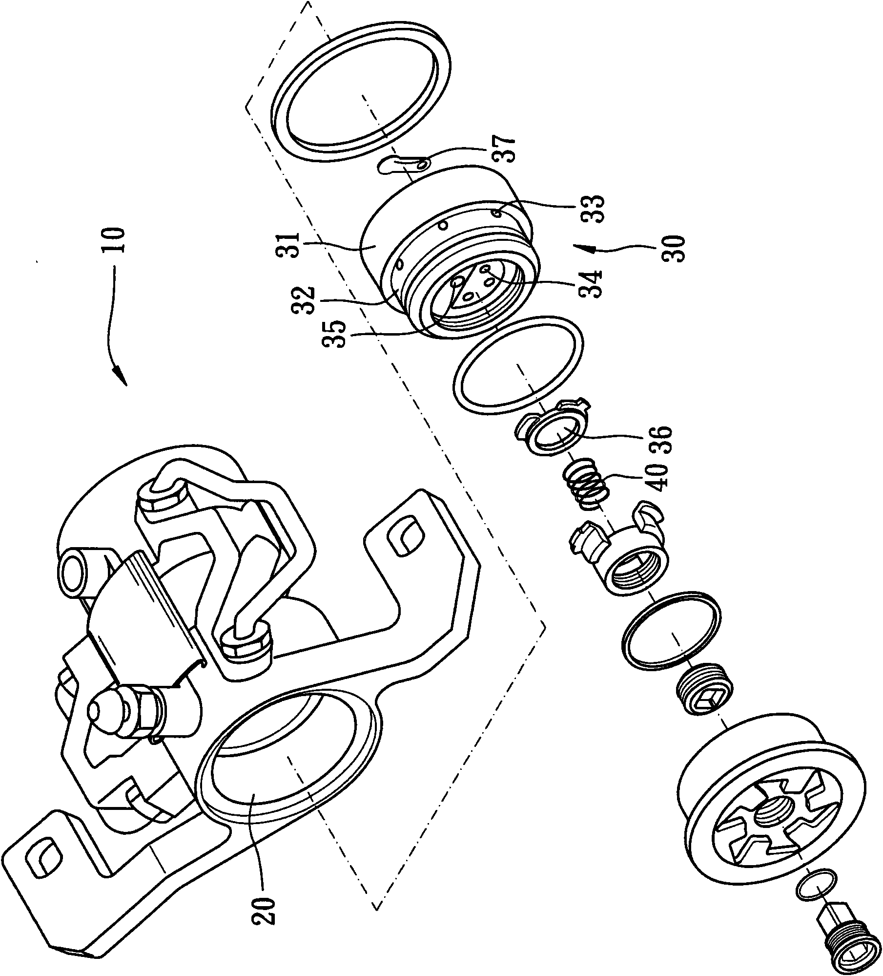
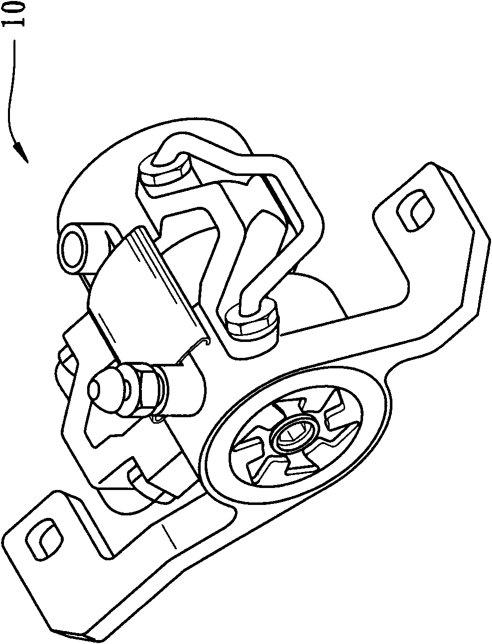
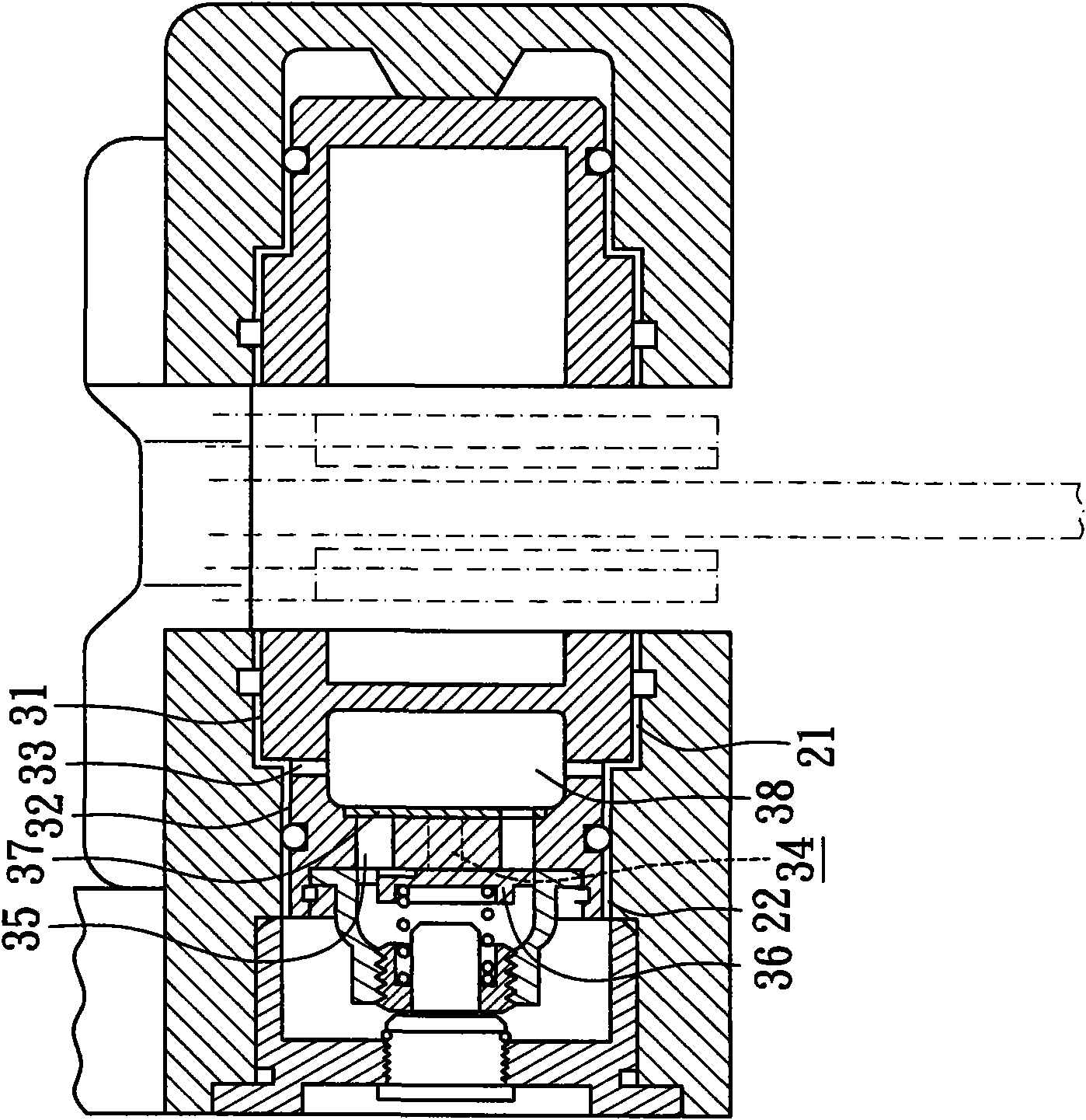
[0040] The present invention relates to a hydraulic cylinder for braking. The present invention can be applied to vehicles such as bicycles and motorcycles. The bicycle is used as an example to illustrate this example. In this embodiment, the hydraulic cylinder is used as a brake caliper 10 as an example. Please refer to Figure 1 to Figure 3 As shown, it includes a first hydraulic cylinder 20 and a first piston 30, wherein:

[0041] The first hydraulic cylinder 20 has an accommodating space, which is transverse to the inside of the first hydraulic cylinder 20, for accommodating the first piston 30 in a movable and sealed manner, and the accommodating space can According to the diameter, it is divided into a first chamber 21 and a second chamber 22, and the diameter of the second chamber 22 is smaller than that of the first chamber 21;

[0042] The first piston 30 has a first part 31 and a second part 32, and the first part 31 and the second part 32 are respectively movable a...


PUM


Abstract

The invention relates to an oil hydraulic cylinder for braking. The oil hydraulic cylinder used for a pair of calipers for braking comprises an oil hydraulic cylinder body and a piston, wherein the oil hydraulic cylinder body is provided with an accommodation space horizontally arranged inside the oil hydraulic cylinder body for accommodating the piston movably in a sealing state. The accommodation space is divided into a first accommodation chamber and a second accommodation chamber, wherein the diameter of the second accommodation chamber is smaller than that of the first accommodation chamber. The piston is provided with a first part and a second part which are respectively and adjacently arranged in the first accommodation chamber and the second accommodation chamber in a movable and sealing state. The oil hydraulic cylinder provides different braking powers of two stages and does not have the phenomenon of deadlock or out of control due to oversized braking power. With simple structure, the oil hydraulic cylinder is easy to manufacture and assemble.

Description

technical field [0001] The invention relates to a braking device, in particular to a hydraulic cylinder for braking with simple structure, low manufacturing cost and two-stage braking functions. Background technique [0002] Existing hydraulic brakes include a brake handle and a brake caliper. The brake caliper is connected to the brake handle through an oil pipe. The brake handle is installed on the handle of a bicycle or motorcycle. The frame or front fork is connected by the oil pipe, and the brake oil is communicated between the brake handle and the brake caliper. The brake handle includes a first hydraulic cylinder and a handle. The handle is connected with the first hydraulic cylinder. A hydraulic cylinder has a first hydraulic cylinder and a first piston, the first piston is arranged in the first hydraulic cylinder, the brake caliper includes a second hydraulic cylinder, the second hydraulic cylinder has A second hydraulic cylinder and a second piston. The second pis...

Claims


Application Information

Patent Timeline
Patent Type & Authority Applications(China)
IPC IPC(8): F16D65/14
Inventor 莫韦恩
Owner ASHIMA LTD
Learn More