
Eureka
For R&D, Eureka makes reading and utilizing patents & technical documents easy.
Eureka AIR
Designed for self-driven R&D workflows. Generate viable solutions, solve complex R&D challenges, empower your innovation with AI.

Eureka Materials
Designed for material experts only. Revolutionize your material R&D, from search, analyze, to developing new materials.

TechResearch
Generate reliable direction feasibility study reports for your R&D in just a few steps.

TechSeek
Discover and master advanced knowledge NOW. Basics, ideas, possibilities, all at once.

TechMind
As an expert in R&D Theories, TechMind can generates customized viable solutions instantly.

TechRisk
Analyze your overall solution with one click, know your potential R&D risks in advance.

TechMonitor
Get weekly tech updates, stay abreast of the latest tech innovations and key insights.
Method, system and device for optimizing route
An optimization method and routing technology, applied in the field of communication, can solve the problems of complex data transmission paths, do not know the MN, and signaling interaction that cannot be optimized for routing, and achieve the effect of simplifying data transmission paths and improving data transmission efficiency.
- Summary
- Abstract
- Description
- Claims
- Application Information
AI Technical Summary
Problems solved by technology
Method used
Image

Examples
Embodiment 1
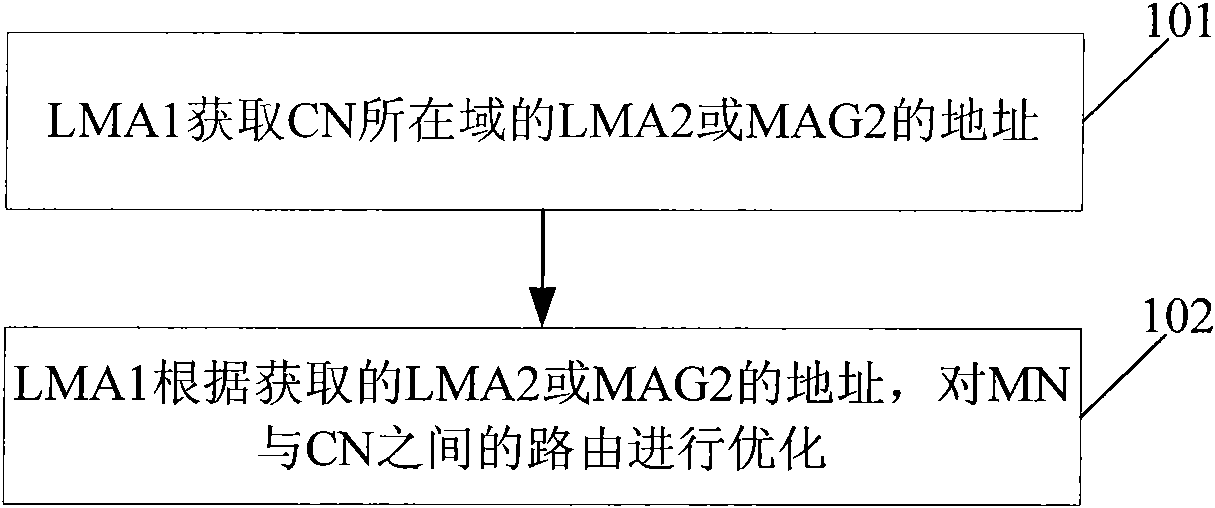
[0042] This embodiment provides a route optimization method, see figure 1 , the present embodiment takes the route optimization initiated by the LMA1 of the domain where the MN is located as an example for illustration, wherein, the MN, MAG1 and LMA1 form the LMA1 domain, and the CN, MAG2 and LMA2 form the LMA2 domain. The method includes:
[0043] 101: LMA1 obtains the address of LMA2 or MAG2 in the domain where CN is located;
[0044] 102: The LMA1 optimizes the route between the MN and the CN according to the acquired address of the LMA2 or MAG2.
[0045]Among them, LMA1 can obtain the address of LMA2 or MAG2 in the domain where the CN is located in various ways, for example: by obtaining the address of the network element device that maintains CN information, such as DNS (Domain Name Server, domain name server), AAA (Authentication, Authorization and Accounting , authentication, authorization and accounting) server, etc., or, according to the address of the CN, send an ad...
Embodiment 2
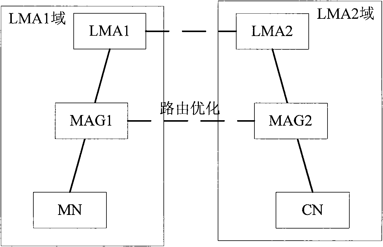
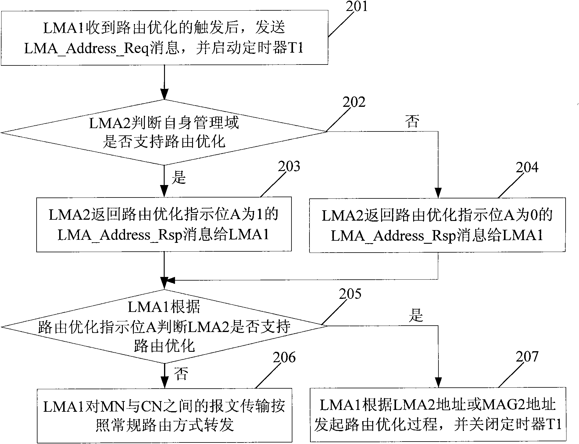
[0057] This embodiment provides a route optimization method, see figure 2 , is a structural diagram of a routing optimization system across LMA domains, wherein MN and CN are two different LMAs under the PMIPv6 domain, MN, MAG1 and LMA1 form the LMA1 domain, and CN, MAG2 and LMA2 form the LMA2 domain. MN's home address (Home Address, HoA) and Proxy-CoA (Care-of-Address, care-of address, that is, the address of MAG1) are registered in LMA1, and CN's HoA and Proxy-CoA (that is, the address of MAG2) are registered in LMA2; This embodiment takes figure 2 LMA1 in the domain where the MN is located in initiates route optimization as an example, see image 3 , routing optimization methods include:
[0058] 201: LMA1 sends an LMA_Address_Req (address request) message and starts a timer T1 after receiving a route optimization trigger (such as a data trigger, an application program trigger, etc.).
[0059] The format of the LMA_Address_Req message is shown in Table 1:
[0060] Tab...
Embodiment 3
[0097] see Figure 5 , this embodiment provides a route optimization system, the system includes: a first local mobility anchor point 401 and a second local mobility anchor point 402, wherein,
[0098] The first local mobility anchor point 401 is used to obtain the address of the second local mobility anchor point or the second mobile access gateway by sending an address request message carrying a hop-by-hop option header, and the source address of the address request message is the first local mobile anchor point The address of the anchor point 401, the destination address is the address of the peer communication node; and according to the address of the second local mobility anchor point 402 or the second mobile access gateway, the routing between the mobile node and the communication node is performed optimization;
[0099] The second local mobility anchor point 402 is configured to receive the address request message carrying the hop-by-hop option header sent by the first...
PUM
 Abstract
Description
Claims
Application Information
 - R&D Engineer
- R&D Manager
- IP Professional
- Industry Leading Data Capabilities
- Powerful AI technology
- Patent DNA Extraction
Browse by: Latest US Patents, China's latest patents, Technical Efficacy Thesaurus, Application Domain, Technology Topic, Popular Technical Reports.
© 2024 PatSnap. All rights reserved.Legal|Privacy policy|Modern Slavery Act Transparency Statement|Sitemap|About US| Contact US: help@patsnap.com