Eureka AIR delivers breakthrough ideas for toughest innovation challenges, trusted by R&D personnel around the world.

Electronic device, non-transitory computer-readable medium storing program, and circuit chip

a technology of non-transitory computer and storing program, applied in the direction of electric digital data processing, instruments, computing, etc., can solve the problems of slow data transfer rate, limited writing time of external storage device, complicated data transfer, etc., to accelerate data transfer, simplify data transmission path, and accelerate data transfer

Inactive Publication Date: 2012-08-14
FUJITSU LTD
View PDF19 Cites 0 Cited by
  • Summary
  • Abstract
  • Description
  • Claims
  • Application Information

AI Technical Summary

Benefits of technology

[0012]Describing the object specifically, a data transmission path is simplified between an external device that supplies data and an external storage device that is a data transfer destination to accelerate the data transfer and to contribute to the reduction of the data writing time in the external storage device.
[0041](2) A data transmission path is simplified between an external device that supplies data and an external storage device that is a data transfer destination to accelerate the data transfer and to contribute to the reduction of the data writing time in the external storage device.

Problems solved by technology

When an electronic device is disposed with a single USB driver as is the case of the portable terminal device, a single interface (I / F) is connected to a USB cable and the data transfer tends to be complicated.
If serial / parallel signals are used for an internal process of the portable terminal device in the data transfer, the rate of the data transfer is reduced due to the data length limitation and clock performance, and the writing time of the external storage device is limited.
Various types of data such as documents, images, videos, music, and game software are transferred from the PC to the external storage device of the portable terminal device, and it is indicated that transferring of an enormous amount of data such as video data or music data takes time.

Method used


Image

  • Electronic device, non-transitory computer-readable medium storing program, and circuit chip
  • Electronic device, non-transitory computer-readable medium storing program, and circuit chip
  • Electronic device, non-transitory computer-readable medium storing program, and circuit chip

Examples


first embodiment

[0064][First Embodiment]

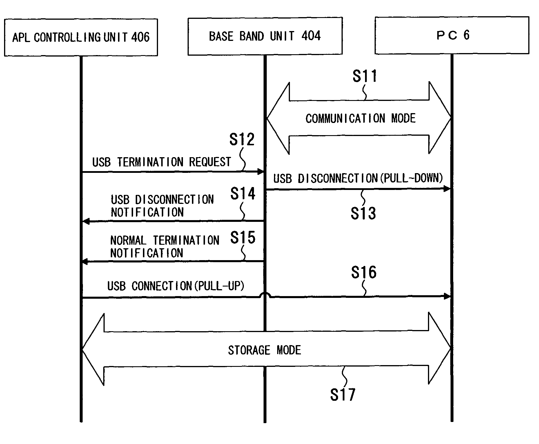
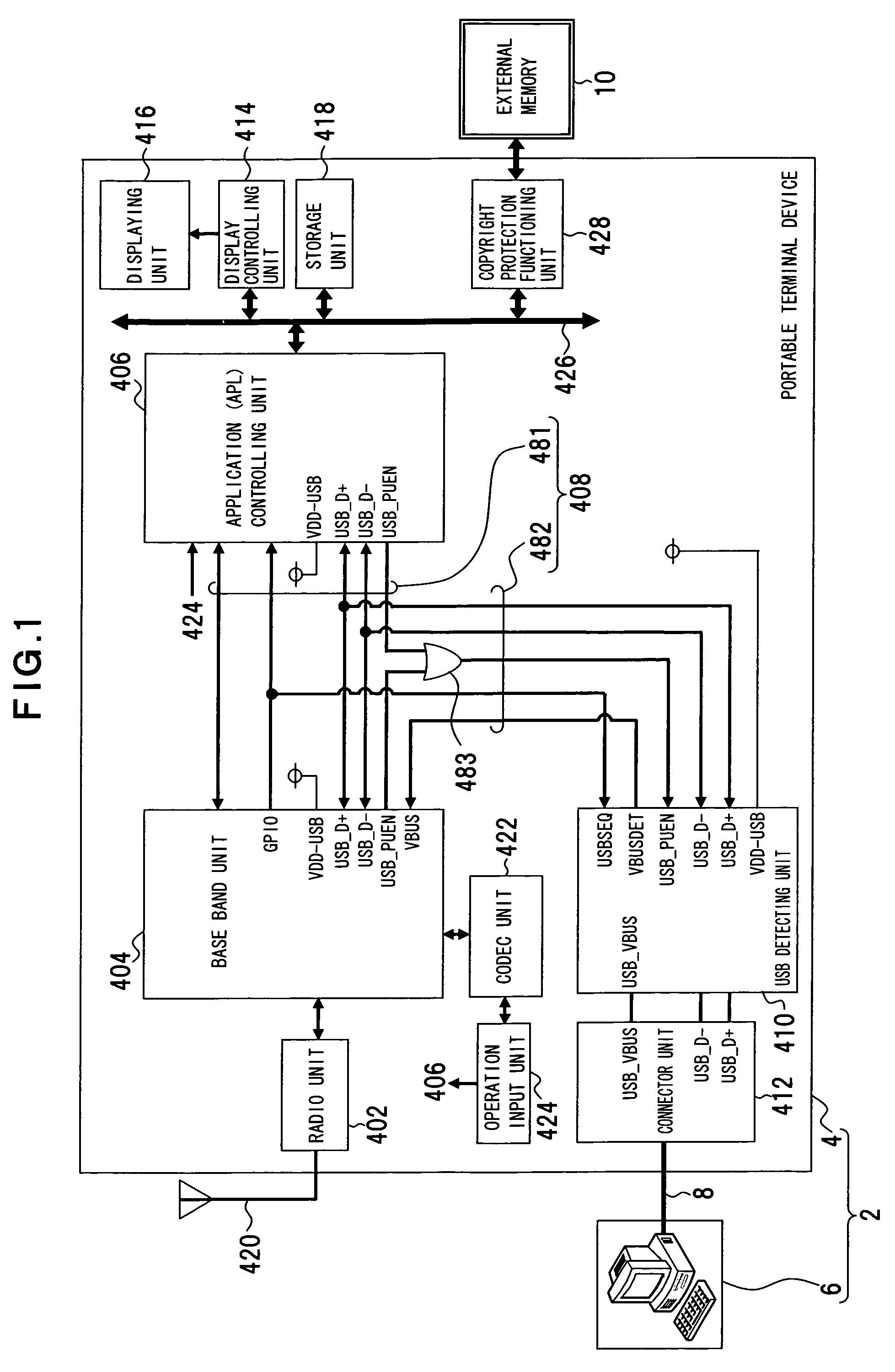
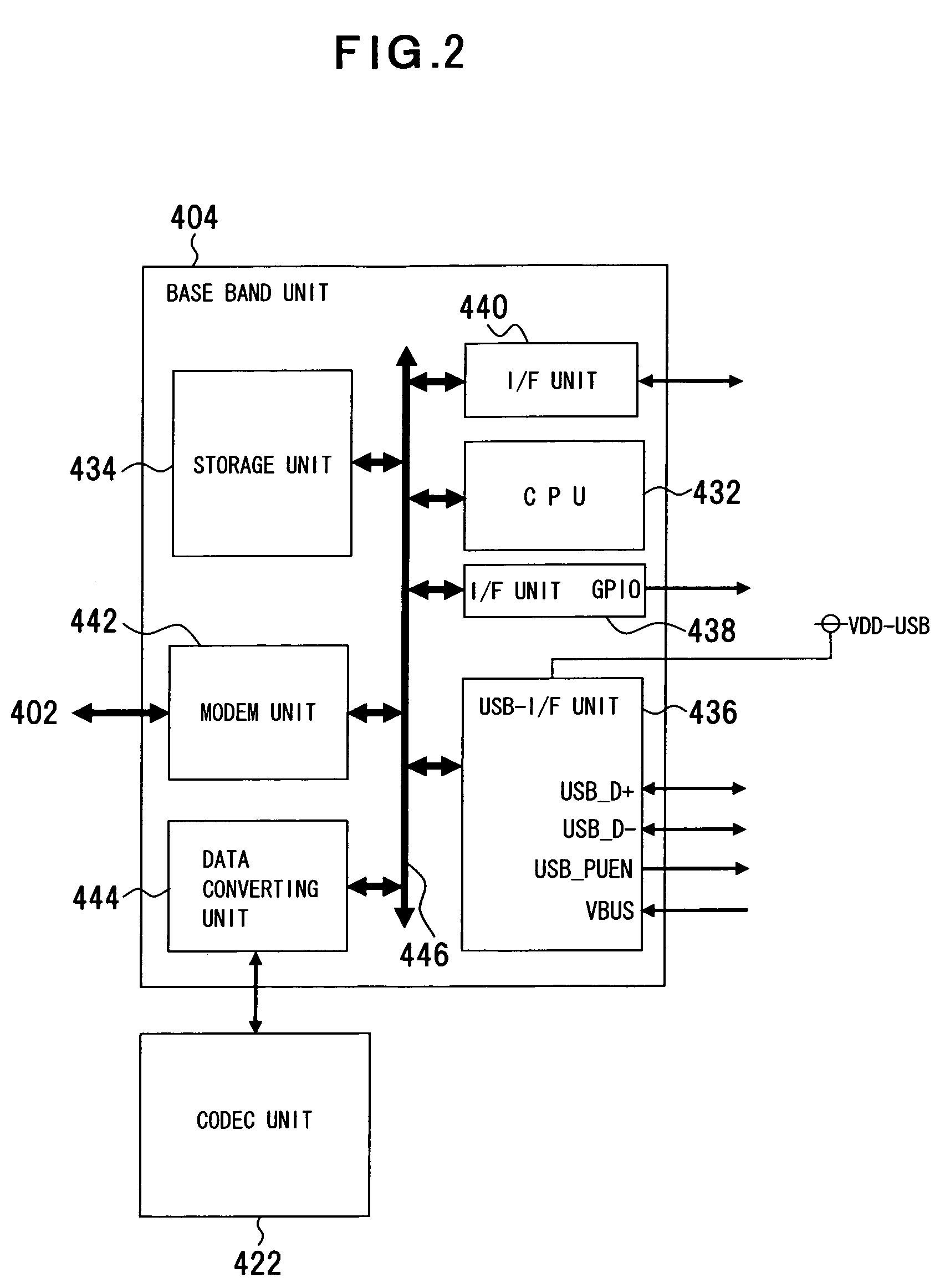
[0065]A first embodiment of the present invention will be described with reference to FIGS. 1 to 9. FIG. 1 shows a data transfer system using a portable terminal device; FIG. 2 shows a configuration example of a base band unit; FIG. 3 shows a configuration example of a storage unit of the base band unit; FIG. 4 shows a configuration example of an application controlling unit; FIG. 5 shows a configuration example of a storage unit of the application controlling unit; FIG. 6 shows an enlarged transfer channel; FIG. 7 shows a configuration example of a USB detecting unit; FIG. 8 shows a configuration example of the portable terminal device; and FIG. 9 shows a configuration example of a personal computer (PC). FIGS. 1 to 9 are an example of the present invention and the present invention is not limited to such configurations.

[0066]This data transfer system 2 connects a portable terminal device 4 and an external device, i.e., a personal computer (PC) 6, with a USB...

second embodiment

[0116][Second Embodiment]

[0117]A second embodiment of the present invention will be described with reference to FIG. 18. FIG. 18 shows an example of a circuit device. In FIG. 18, the same reference numerals are added to the same portions as FIG. 1.

[0118]This circuit device includes the aforementioned radio unit 402, the base band unit 404, the APL controlling unit 406, the transmitting channel 408, the USB detecting unit 410, the display controlling unit 414, the storage unit 418, the codec unit 422, and the copyright protection functioning unit 428 on a single circuit substrate 40. Such a configuration can be disposed on the aforementioned portable terminal device 4 to realize functions such as the aforementioned data transfer control.

[0119]As shown by dotted lines of FIG. 18, the circuit substrate 40 may include the connector unit 412 and the displaying unit 416.

third embodiment

[0120][Third Embodiment]

[0121]A third embodiment of the present invention will be described with reference to FIG. 19. FIG. 19 shows a configuration example of a control circuit chip. In FIG. 19, the same reference numerals are added to the same portions as FIG. 1.

[0122]The portable terminal device 4 of this embodiment uses a control circuit chip 405 constituted by integrating the base band unit 404 and the APL controlling unit 406, and this control circuit chip 405 is disposed with a portion of the bus 482 along with the bus 481 of the transmission channel 408 described above.

[0123]By using such a control circuit chip 405, various functions such as the aforementioned data transfer control can also be realized.

[0124][Other Embodiment]

[0125](1) Although the portable terminal device 4 constituting a cellular phone is illustrated as the electronic device in the embodiments, the present invention can be applied to a personal digital assistant (PDA) 12 that is an electronic device connec...


PUM


Abstract

The present invention relates to data transfer to an external storage device disposed on or connected to an electronic device and can accelerate the data transfer. The present invention relates to an electronic device (portable terminal device) connected or disposed with an external storage device, includes a transmission channel connected to an external device (personal computer) that is a data source to transmit data, and simplifies a data transmission path intervening between the transmission path and the external storage device to accelerate the data transfer and accelerate the writing of data into the external storage device.

Description

CROSS-REFERENCE TO RELATED APPLICATIONS[0001]This application is based upon and claims the benefit of priority from the prior Japanese Patent Application No. 2006-114832, filed on Apr. 18, 2006, the entire contents of which are incorporated herein by reference.BACKGROUND OF THE INVENTION[0002]1. Field of the Invention[0003]The present invention relates to an electronic device disposed or connected with an external storage device such as the SD (Secure Digital) memory card and, particularly, relates to an electronic device, a data transfer controlling method thereof, a data transfer controlling program thereof, a circuit chip, a circuit device, and a data transfer system that can use an interface function of USB (Universal Serial Bus), etc., to transfer data to an external storage device for writing of data.[0004]2. Description of the Related Art[0005]In a method of writing application data, etc., externally into an external storage device disposed on a portable terminal device such ...

Claims


Application Information

Patent Timeline
Patent Type & Authority Patents(United States)
IPC IPC(8): G06F13/00
CPCH04M1/72527H04M1/72409
Inventor UCHIDA, HIROYUKISHIDA, ISAMU
Owner FUJITSU LTD
Why Eureka
Eureka Blog
Learn More