Method for driving scan line
A driving method and scanning line technology, applied in the direction of instruments, static indicators, etc., can solve the problems of poor display effect, decreased display aperture ratio, unable to reach the data voltage level, etc.
- Summary
- Abstract
- Description
- Claims
- Application Information
AI Technical Summary
Problems solved by technology
Method used
Image
Examples
no. 1 example
[0028] Please refer to Figure 4 , which shows a waveform diagram of scanning signals according to the scanning line driving method in the first embodiment of the present invention. In this embodiment, two scan signals SD1' and SD2' are taken as an example to illustrate the scan signals driving the odd scan line 310a and the even scan line 310b.
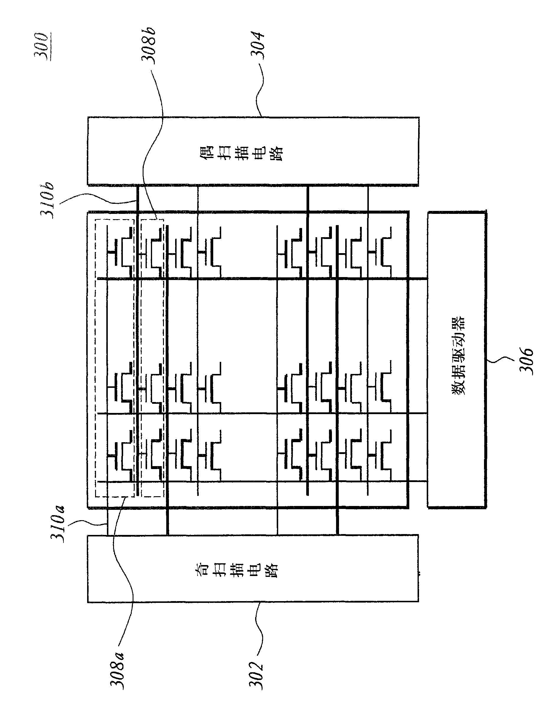
[0029] Such as Figure 4 As shown, this embodiment is applied to a liquid crystal display 300, and the odd scan circuit 302 and the even scan circuit 304 are used to generate scan signals SD1' and SD2' respectively. The scan signals SD1' and SD2' are used to control the odd-numbered pixel 308a and the even-numbered pixel 308b through the odd scan line 310a and the even scan line 310b, respectively.
[0030] The liquid crystal display 300 includes an odd frame scan period and an even frame scan period due to the polarity inversion of the data voltage. During the scanning period of the odd frame, the pixels 308a in the odd columns a...
no. 2 example
[0041] Please refer to Figure 7 , which shows a scanning signal waveform diagram according to the scanning line driving method in the second embodiment of the present invention. In this embodiment, the scanning signals SD1 ″ and SD2 ″ are used to represent the scanning signals for driving the odd scanning line 310 a and the even scanning line 310 b respectively, and taking the scanning signals SD1 ″ and SD2 ″ as an example, for the odd scanning line 310 a and the even scanning line 310 a The scanning signal of the scanning line 310b will be described.
[0042] The difference between the second embodiment and the first embodiment is that the scanning signals SD1 ″ and SD2 ″ in the second embodiment have different timing waveforms from the scanning signals SD1 ′ and SD2 ′ in the first embodiment, such as Figure 7 The scanning line driving method of this embodiment shown is to cut the pixel scanning time TS of the odd scanning line 310a and the even scanning line 310b among th...
no. 3 example
[0063] Please refer to Figure 11 , which shows a waveform diagram of scanning signals according to the scanning line driving method in the third embodiment of the present invention. The scanning line driving method of the third embodiment is applied to the liquid crystal display 300 . In this embodiment, the N columns of pixels 308 of the LCD 300 are controlled by cutting the pixel scanning time TS of the N scanning lines 310 in the LCD 300 to achieve the effects of pre-charging and pre-discharging. This embodiment takes four scan lines as an example to illustrate the operation method of N scan lines 310 in the liquid crystal display 300 .
[0064] The scan signals SD1 ″’ and SD3 ″’ are generated by the odd scan circuit 302 , and the scan signals SD2 ″’ and SD4 ″’ are generated by the even scan circuit 304 . The scan signals SD1"' and SD3"' are used to respectively control the first and third columns of pixels in the odd columns of pixels 308a through the first scan line an...
PUM
 Abstract
Description
Claims
Application Information
 - R&D
- Intellectual Property
- Life Sciences
- Materials
- Tech Scout
- Unparalleled Data Quality
- Higher Quality Content
- 60% Fewer Hallucinations
Browse by: Latest US Patents, China's latest patents, Technical Efficacy Thesaurus, Application Domain, Technology Topic, Popular Technical Reports.
© 2025 PatSnap. All rights reserved.Legal|Privacy policy|Modern Slavery Act Transparency Statement|Sitemap|About US| Contact US: help@patsnap.com


