Rubber water injection core mould

A rubber and mandrel technology, applied in ceramic forming cores, ceramic forming mandrels, ceramic forming machines, etc., can solve the problems of time-consuming and labor-intensive, low production efficiency, poor processing accuracy, etc. simple structure

Inactive Publication Date: 2010-01-06
叶荣近
View PDF0 Cites 6 Cited by
  • Summary
  • Abstract
  • Description
  • Claims
  • Application Information

AI Technical Summary

Problems solved by technology

The mandrel is composed of multiple split molds combined at different angles. It is combined during production and broken into parts during demoulding. The whole process is time-consuming

Method used


Image

  • Rubber water injection core mould
  • Rubber water injection core mould

Examples


Embodiment Construction

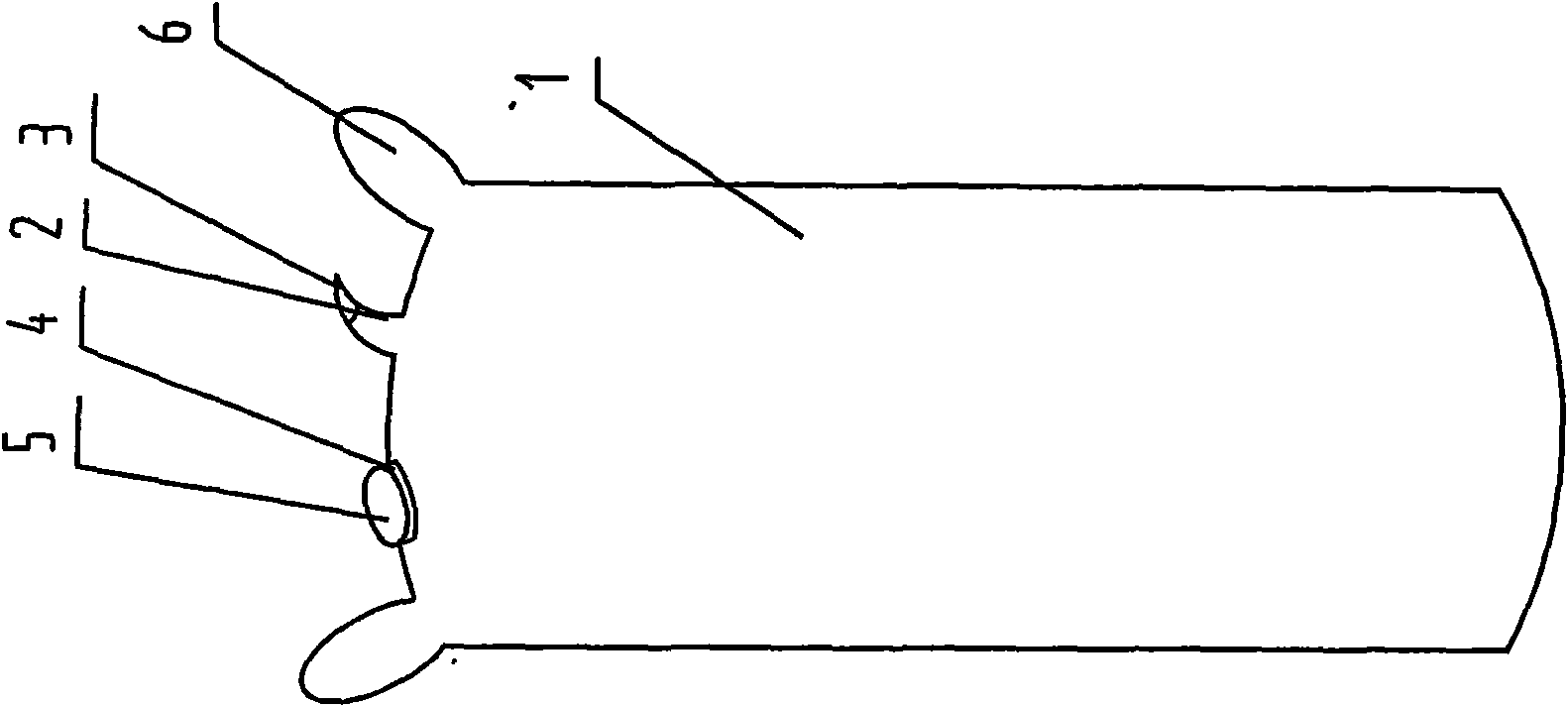
[0011] As shown in the figure, a rubber water injection mandrel is characterized in that: an inlet and exhaust nozzle 2 is installed on the top of the rubber water injection mold body 1, an upper cover 3 is placed on the inlet and outlet nozzle 2, and a rubber water injection mold body 1 The top of the top is also equipped with inlet and outlet ports 4, and the inlet and outlet ports are processed with threads, which are matched with a nozzle cover 5 with internal threads, and lifting lugs 6 are installed on both sides of the top of the rubber water injection mold body 1 to prevent the core mold from The core mold shifts due to different pouring bodies.

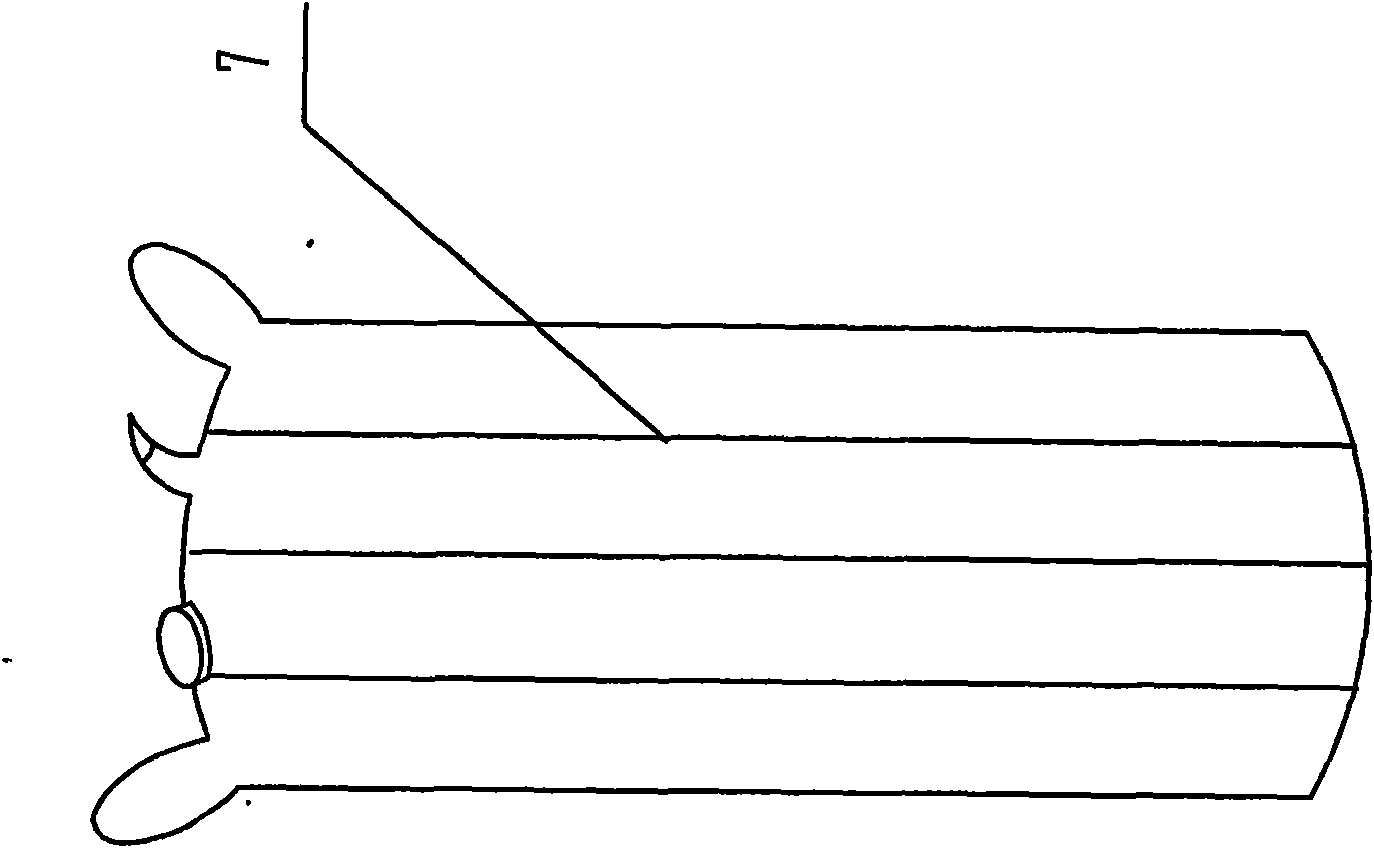
[0012] The rubber water injection mold body 1 is processed with reinforcing ribs 7, and the bottom of the rubber water injection mold body 1 is processed into a slightly arc or flat bottom.

[0013] When working, enter water at 4 inlets and outlets to fill the rubber water injection mandrel with water. After the workpiece is ...


PUM


Abstract

The invention relates to a mould for manufacturing hollow pipes and hollow-structure sheets, in particular to a rubber water injection core mould. The top end of a rubber water injection mould body is provided with an air inlet and exhaust nozzle; an upper cover is arranged on the air inlet and exhaust nozzle; the top end of the rubber water injection mould body is provided with a water inlet and outlet port which is provided with screw threads; a water port cover with internal threads is matched with the water inlet and outlet port; and both sides of the top end of the rubber water injection mould body are provided with hanging lugs. When the rubber water injection core mould is used, wateris injected into the rubber water injection mould from the water inlet and outlet port, and after a workpiece is molded, water is discharged from the water inlet and outlet port, so that the core mould can be conveniently drawn out of the hardened workpiece. The core mould is made of rubber and can be used repeatedly, thus the production cost is reduced.

Description

technical field [0001] The invention relates to a mold for producing and processing hollow pipes and hollow plates, in particular to a rubber water injection mandrel. Background technique [0002] At present, the production and processing of hollow pipes and hollow plates such as concrete drainage pipes, glass steel pipes, and building hollow slabs, etc., most of the mandrels used are integrated mandrels or multi-piece mandrels assembled into an integral mandrel. The clamping force pulls the mandrel out of the product. The mandrel is composed of multiple split molds combined at different angles. It is combined during production and broken into parts during demoulding. The whole process is time-consuming and laborious, and the processing accuracy is relatively poor. The labor intensity of workers is high and the production efficiency is low. So far, there is no such thing as Great solution. Contents of the invention [0003] In order to overcome the shortcomings of the ab...

Claims


Application Information

Patent Timeline
IPC IPC(8): B28B7/32B28B7/34
Inventor 叶荣近
Owner 叶荣近
Why Eureka
Try Eureka