
Device for lifting reverse roller of loom

A technology of reverse rollers and looms, which is applied to auxiliary equipment for weaving, textiles, textiles, and papermaking. It can solve the problems of large damage to the lifting device of the reverse roller, heavy weight, and deterioration of the workability of the warp reel. Save manpower, reduce risks, and improve workability

Active Publication Date: 2010-01-06
TSUDAKOMA KOGYO KK
View PDF1 Cites 2 Cited by
  • Summary
  • Abstract
  • Description
  • Claims
  • Application Information

AI Technical Summary

Problems solved by technology

In particular, the weight of the fully wound warp reel is heavy. In addition to the difficulty in the operation of the reel running car, in the case of a collision due to misoperation, the damage of the reverse roller lifting device or the damage of the flange is large, so it requires work. Operators carefully operate the reel transfer vehicle, which deteriorates the workability of warp reel replacement

Method used


Image

  • Device for lifting reverse roller of loom
  • Device for lifting reverse roller of loom
  • Device for lifting reverse roller of loom

Examples


Embodiment Construction

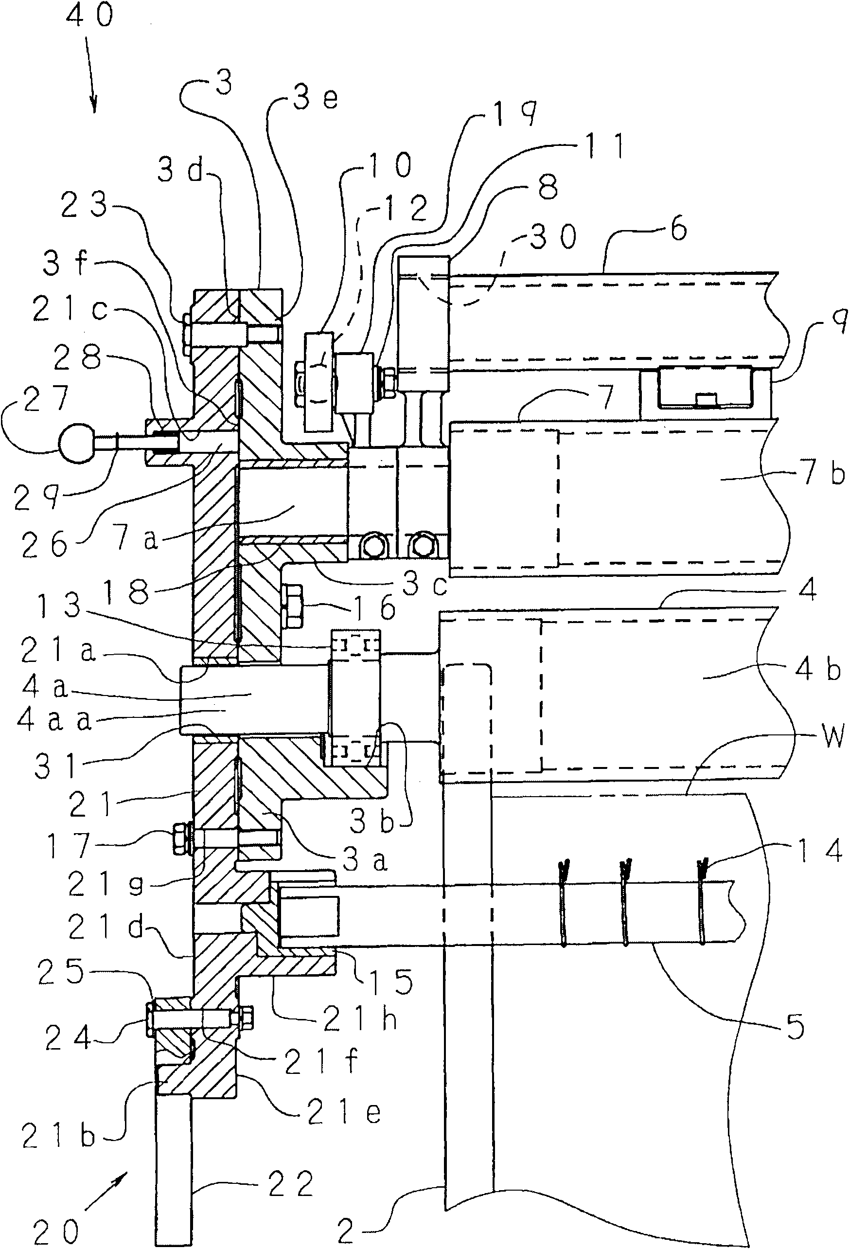
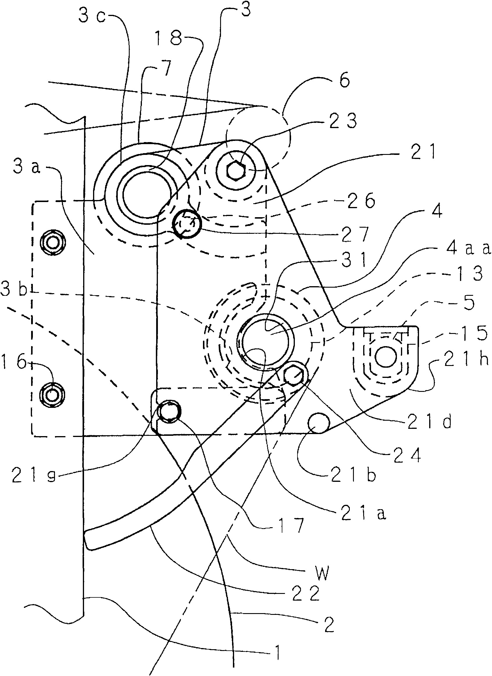
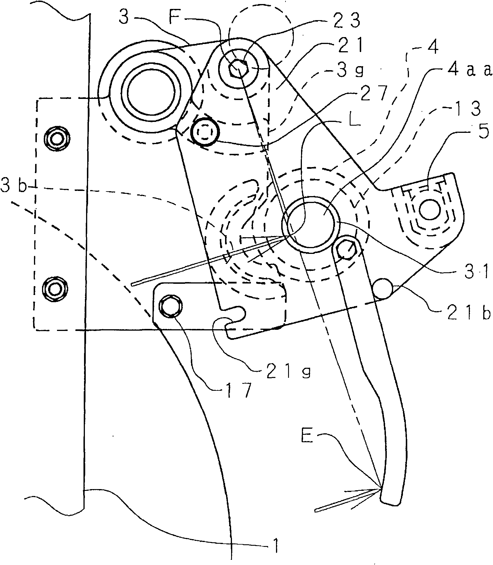
[0023] Embodiments of the present invention will be described below with reference to the drawings. figure 1 It shows the delivery device on the right side viewed from the winding side of the loom, and shows a rear view of the reverse roller lifting device 40 of the delivery device viewed from the rear side of the loom. In addition, in order to show overlapping parts that cannot be seen, the position and shape of each part are shown in the direction perpendicular to the fabric width direction in which the reverse roller 4 extends, that is, in the front-rear direction of the loom viewed from the winding side. Appropriate changes are made to depict. figure 2 From figure 1The side view seen on the left side of , shows the counter roll lifting device 40 in operation of the loom. except not depicted figure 1 Shown end support 8, middle part support 9, spherical surface bearing unit 10, loosening distribution pin 11, loosening warp bar 12, outside loosening warp lever 19, depict...


PUM


Abstract

The present invention provides a device for lifting a reverse roller of a loom without worry of chaine winding shaft collision when carrying the chaine winding shaft for replacement. Right and left frames of the loom are provided with circular bearing supporting seats respectively, bearings jogged on two ends of the reverse roller are supported on the bearing supporting seats. The device for lifting the reverse roller and holding on a back-off position is provided with a pair of projecting parts arranged on a shaft part of two ends of the reverse roller and extending from a jogged part of the bearing toward the axial direction, and a pair of lifting rods supported asway on the external side of the bearing supporting seat respectively, wherein the pair of the lifting rods cooperate with the pair of the projecting parts to lift the reverse roller and hold on the back-off position.

Description

technical field [0001] The present invention relates to a reverse roll lifting device for lifting a reverse roll around which a warp yarn from a warp yarn reel is wound and holding it at a retracted position. Background technique [0002] The reverse roll is rotatably arranged at an upper position on the rear side than the warp yarn reel when viewed from the winding side of the loom. The warp yarn from the warp spool is hung on the counter roll and guided to the let-off roll. The easing roller swings in the front and back directions of the loom, and performs easing motion. Suppresses changes in warp tension following warp shedding movement of the heddle. The diameter of the flange of the warp reel increases with the increase of the volume, and when it is placed on the reel transfer cart for replacement, the flange interferes with the reverse roller. Therefore, every time the warp yarn reel is replaced, it is necessary to disassemble and install the reverse roller. [000...

Claims


Application Information

Patent Timeline
Patent Type & Authority Applications(China)
IPC IPC(8): D03J1/00
Inventor 角田博
Owner TSUDAKOMA KOGYO KK
Learn More