Device for switching on and off an electric circuit

A technology for connecting circuits and circuits, applied in the direction of using switches to cut off batteries, circuits, relays, etc., which can solve problems such as failures and wear of mechanical devices

Inactive Publication Date: 2010-01-06
SCHNEIDER ELECTRIC IND SAS
View PDF1 Cites 2 Cited by
  • Summary
  • Abstract
  • Description
  • Claims
  • Application Information

AI Technical Summary

Problems solved by technology

[0003] In order to control the ignition of the gunpowder, the device of the prior art requires the use of an external

Method used


Image

  • Device for switching on and off an electric circuit
  • Device for switching on and off an electric circuit
  • Device for switching on and off an electric circuit

Examples


Embodiment Construction

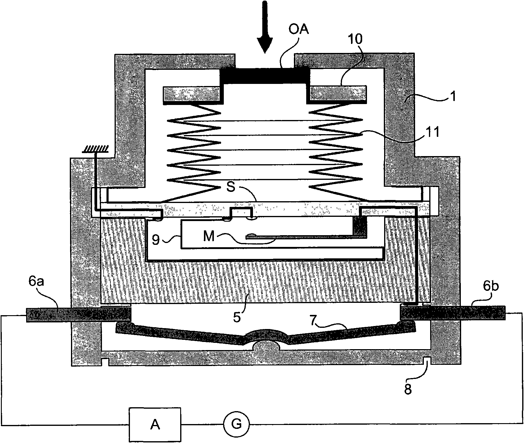
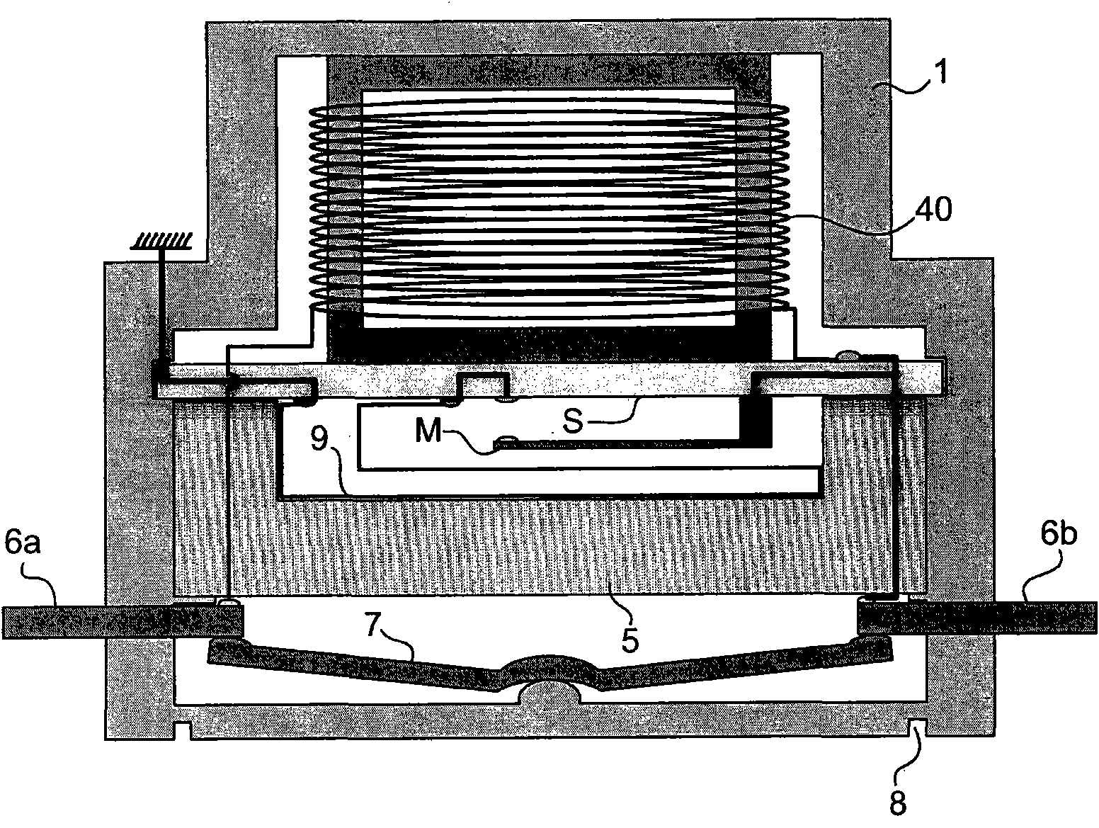
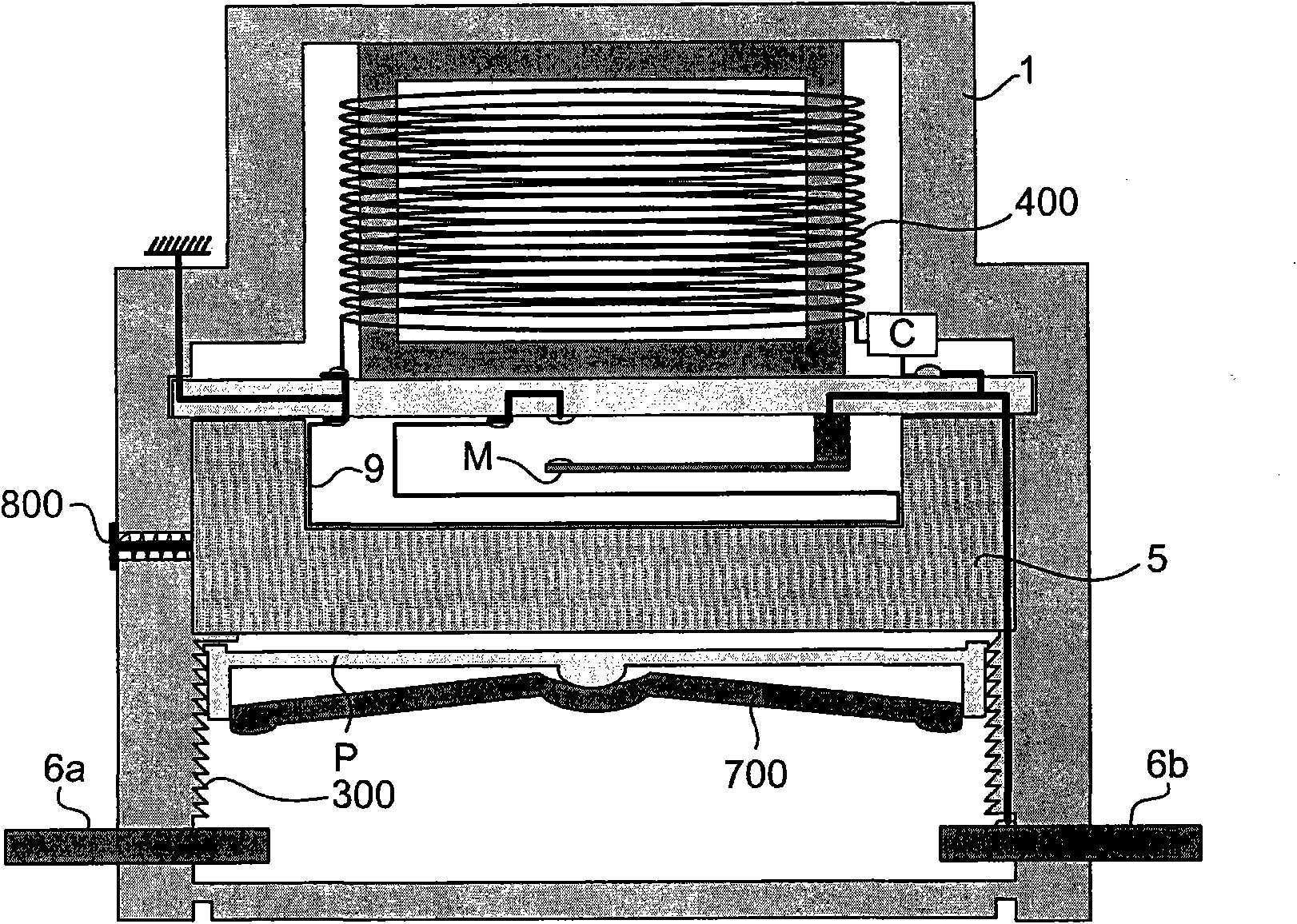
[0024] The invention relates to a device for interrupting or switching on a main circuit. The main circuit may for example be reserved for energizing batteries, transformers, lift brakes, or any type of circuit that needs to be quickly and reliably broken or made.

[0025] figure 1 and 2 interrupt device shown as well as image 3 Each of the communication means shown comprises a body 1 passed through by two electrical conductors 6a, 6b spaced apart and connected to the mains electricity of the device A, for example supplied by a generator G supply circuit ( figure 1 ). In an interrupting device, the two conductors 6a, 6b are initially connected by a connecting piece 7, which is displaceable so that an electrical connection is initially made, while in a connecting device, the two conductors 6a, 6b are initially spaced apart And designed to be connected by a displaceable connecting piece 700 . The body 1 of the device is sealed and comprises a bottom wall on which a fractu...


PUM


Abstract

The invention relates to a device for switching on and off an electric circuit comprising: a charge (5) which can be ignited, the combustion of which brings about the switching on or off of the electric circuit, ignition means for the pyrotechnic charge (5), characterised in that: the ignition means are connected to the electric circuit and the ignition means comprise a microswitch (M, M') with magnetic action for controlling the ignition of the pyrotechnic charge (5).

Description

technical field [0001] The invention relates to devices for breaking / making electrical circuits. The device operates on the basis of pyrotechnic charges. Background technique [0002] In particular, known from document DE4406730 is a device for interrupting electric circuits. In particular, the device comprises a pyrotechnic actuator comprising a powder and a piston whose translational movement is controlled under the influence of gases produced by the combustion of the powder. The piston has fingers that can bear on a connecting bridge that initially provides an electrical connection between the two conductors. The bridge is mounted on springs. In operation, the gases produced by the combustion of the gunpowder cause the movement of the piston, which pushes on the bridge to break the two conductors, thereby interrupting the electrical circuit. [0003] In order to control the ignition of the powder, this prior art device requires the use of an external detection member....

Claims


Application Information

Patent Timeline
IPC IPC(8): H01H39/00
CPCH01H35/14H01H2050/007H01H39/004H01H50/005H01H36/00H01H35/144H01H35/24H01H2039/008H01H2036/0093H01H39/00H01H59/0009H01H39/006
Inventor 休格斯·菲利普提马塞厄斯·拉米恩
Owner SCHNEIDER ELECTRIC IND SAS
Why Eureka
Try Eureka