
Straight panel type bushing plate

A drilling template and straight plate technology, which is applied to the drilling template for workpieces and other directions, can solve problems such as structural defects, affecting workpiece clamping efficiency and fixture accuracy, fixture measurement, and inconvenience in inspection, so as to simplify assembly steps and ensure product quality. , the effect of shortening the assembly time

Inactive Publication Date: 2010-01-13
SHENYANG AIRCRAFT CORP
View PDF0 Cites 8 Cited by
  • Summary
  • Abstract
  • Description
  • Claims
  • Application Information

AI Technical Summary

Problems solved by technology

[0002] At present, the application of the hole system combination fixture has solved many technical problems such as precision, rigidity, and strength for us; but when processing parts with multiple rows of holes and high coaxiality requirements, due to the structural defects of the existing drilling template components , the tool guide mechanism cannot be directly installed in multiple layers. In order to meet the technical requirements in the process of assembling the fixture, the problem must be solved through 90°, 180° direction dislocation assembly and coordinate offset, which directly affects the workpiece clamping efficiency and fixture accuracy. Many inconvenient factors have been derived from the measurement and inspection of the fixture, which restrict the application and development of the hole system combination fixture in production

Method used


Image

  • Straight panel type bushing plate
  • Straight panel type bushing plate
  • Straight panel type bushing plate

Examples


Embodiment Construction

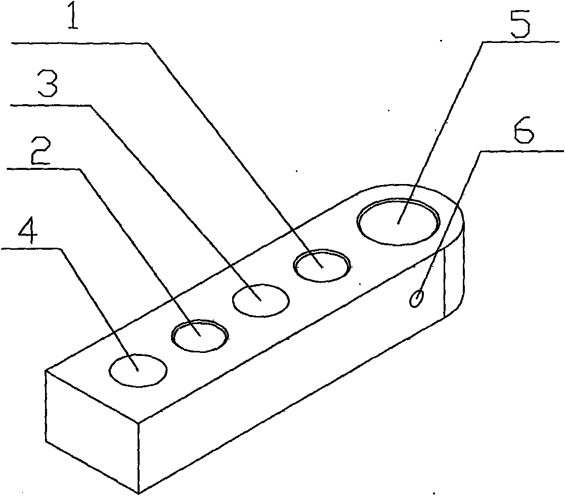
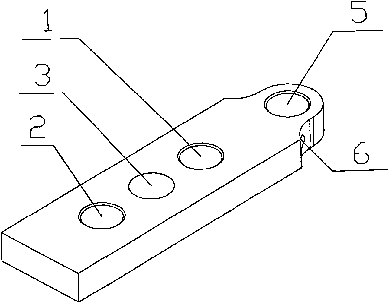
[0013] Straight plate drilling template, including template body, is characterized in that a guide hole is made at one end of the template body, and 2 positioning pin holes and 1 or 2 bolt holes are made on the template body. The arrangement of the two holes is from the guide hole Start as a dowel hole, a bolt through hole, a dowel hole, a bolt through hole, make a threaded hole perpendicular to the guide hole between the guide hole and the dowel hole, the threaded hole is tangent to the guide hole.

[0014] The guide hole is made into Φ12H7 or Φ18H7.

[0015] The positioning pin hole is made into Φ12H7, and the hole distance is 40±0.01mm.

[0016] The distance between the guide hole and the positioning pin hole is 25±0.01mm, 35±0.01mm or 55±0.01mm.

[0017] The bolt hole is made Φ13mm, the hole distance is 40±0.01mm, and the hole distance from the positioning pin hole is 20mm.

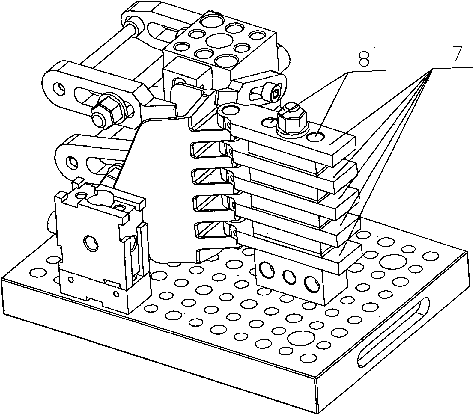
[0018] Application examples such as image 3 As shown, in order to make the holes of the lugs o...


PUM


Abstract

The invention discloses a straight panel type bushing plate which is used on a hole-series modular fixture and is an element used for ensuring the concentricity of a plurality of holes on a workpiece during processing, such as drilling, expanding or reaming and the like. The straight panel type bushing plate comprises a bushing plate body, a leading hole is manufactured on one end of the bushing plate body, and two positioning pin holes and one or two bolt passing holes are manufactured on the bushing plate body; the arrangement of two kinds of holes is as follows: a positioning pin hole, a bolt passing hole, a positioning pin hole and a bolt passing hole are arranged in order from the leading hole, a thread hole vertical to the leading hole is manufactured between the leading hole and the positioning pin hole, and the thread hole and the leading hole are tangent. The invention has the advantages that a plurality of straight panel type bushing plates can be simultaneously adopted for assembling multiple layers of leading structures to realize the functions of drilling, reaming, leading or stitching; a function simplifying and assembling step which can replace special pieces is used for shortening assembly time and ensuring product quality; the invention can be arbitrarily matched with supporting pieces, gaskets, guidance supporting pieces, displacement supporting pieces and the like in the combined fixture to realize the functions of positioning, orientation and integral displacement.

Description

Technical field: [0001] The invention is an element used in the combined hole system fixture to ensure the coaxiality of multiple holes on the workpiece during drilling, expanding or reaming, and to play the role of positioning, guiding and guiding. Background technique: [0002] At present, the application of the hole system combination fixture has solved many technical problems such as precision, rigidity, and strength for us; but when processing parts with multiple rows of holes and high coaxiality requirements, due to the structural defects of the existing drilling template components , the tool guide mechanism cannot be directly installed in multiple layers. In order to meet the technical requirements in the process of assembling the fixture, the problem must be solved through 90°, 180° direction dislocation assembly and coordinate offset, which directly affects the workpiece clamping efficiency and fixture accuracy. There are many inconvenient factors derived from the ...

Claims


Application Information

Patent Timeline
IPC IPC(8): B23B47/28
Inventor 王金财王环文靖
Owner SHENYANG AIRCRAFT CORP
Learn More