
Vehicle roof mount antenna

A technology for antennas and car roofs, applied to antennas, antenna parts, antenna supports/mounting devices, etc., can solve the problems of not being able to guarantee water resistance and dust resistance, so as to prevent deformation of the car roof, ensure water resistance and water resistance dusty effect

Active Publication Date: 2010-01-13
HARADA IND CO LTD
View PDF2 Cites 2 Cited by
  • Summary
  • Abstract
  • Description
  • Claims
  • Application Information

AI Technical Summary

Problems solved by technology

Specifically, there is a gap between the annular rib away from the protrusion and the roof, so that satisfactory waterproofness and dustproofness cannot be guaranteed

Method used


Image

  • Vehicle roof mount antenna
  • Vehicle roof mount antenna
  • Vehicle roof mount antenna

Examples


Embodiment Construction

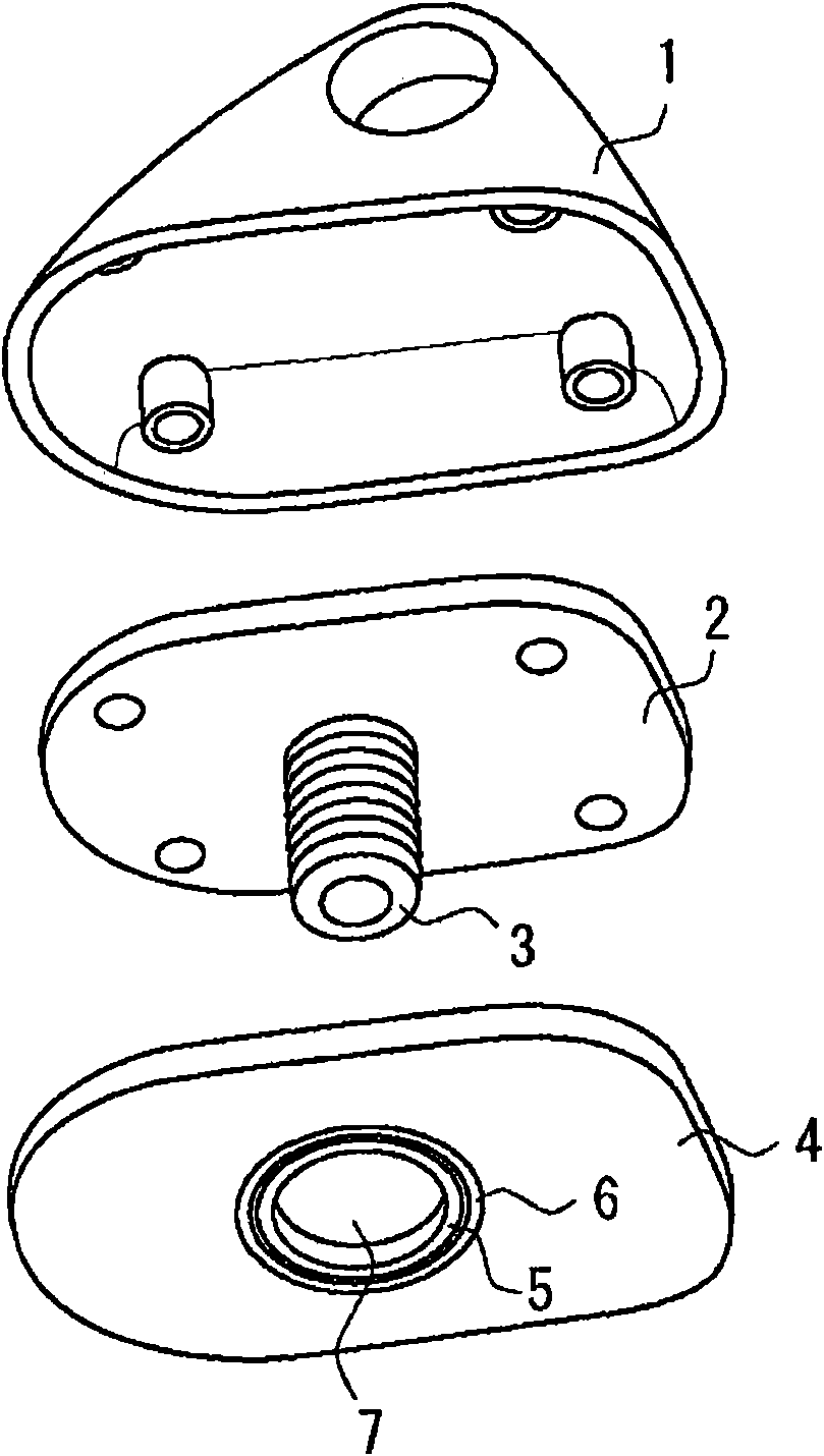
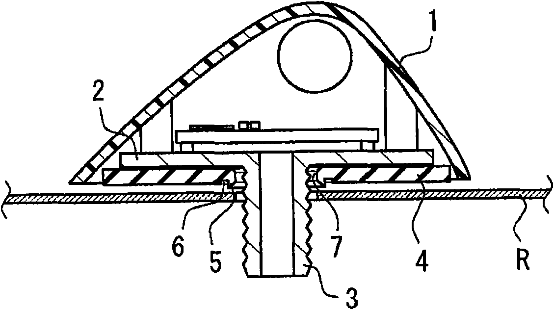
[0019] Preferred embodiments of the present invention are described below with reference to the accompanying drawings. figure 1 is an exploded perspective view of the roof mount antenna according to the first embodiment of the present invention. figure 2 is a vertical cross-sectional view of the roof-mounted antenna according to the first embodiment. As shown in the figure, the roof mount antenna according to the present invention is mainly composed of an antenna cover 1, an antenna base 2, a protrusion 3, a pad 4, an annular rib (flange) 5, and an annular groove portion 6.

[0020] The antenna cover 1 defines the appearance of the roof-mounted antenna according to the present invention. The shape of the antenna cover of the roof-mounted antenna according to the present invention is not limited to the shape shown in the drawings, but may be modified according to desired functions or designs.

[0021] The antenna base 2 is covered by the antenna cover 1 . Circuit boards, an...


PUM


Abstract

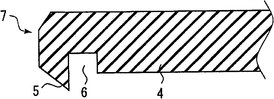
The vehicle roof mount antenna to be detachably mounted on a vehicle roof is mainly constituted by an antenna cover 1, an antenna base 2, a boss 3, a pad 4, an annular rib 5, and an annular groove portion 6. The pad 4 has a boss hole 7 through which the boss 3 penetrates and is disposed between the antenna base 2 and the vehicle roof R. The annular rib 5, which is made of an elastic material, is provided on the vehicle roof R side surface of the pad 4. When the vehicle roof mount antenna is fixed to the vehicle roof R, the annular rib 5 is inclined from the boss hole 7 toward a periphery of the pad 4. The annular groove portion 6 is provided at a position where the pressing force of the annular rib 5 against the vehicle roof R can be reduced. Thus, even when the vehicle roof on which the roof mount antenna device is mounted has a small thickness, it is possible to prevent the vehicle roof from being deformed while ensuring waterproofness and dustproofness.

Description

[0001] related application [0001] This application is related to Japanese Patent Application No. 2008-178412 filed on July 8, 2008, and claims the priority of the Japanese Patent Application. technical field [0002] The present invention relates to a roof mount antenna detachably mounted on a roof of a vehicle, and more particularly to a roof mount antenna with improved water resistance and dust resistance. Background technique [0003] Roof mount antennas typically have pads on the surface that contacts the roof of the vehicle. The gasket has an annular rib (flange) made of elastic material to improve water and dust resistance. The raised mounting pressure brings the annular rib of the pad into press contact with the roof, thereby ensuring the waterproof and dust-proof properties of the roof-mounted antenna. [0004] For example, Patent Document 1 (Japanese Patent Application Laid-Open No. 2005-102031) discloses an antenna for automobiles. The antenna has a pad in whi...

Claims


Application Information

Patent Timeline
Patent Type & Authority Applications(China)
IPC IPC(8): H01Q1/32H01Q1/42B60R11/02H01Q1/22
CPCH01Q1/1214H01Q1/3275H01Q1/22H01Q1/32H01Q5/00
Inventor 小林秀和皆川光男大场智史林信横山敏郎
Owner HARADA IND CO LTD
Learn More