
Foldable backboard structure and display device

A technology for display devices and backplanes, which is applied in the direction of identification devices, instruments, etc., can solve problems such as ripples, achieve the effect of reducing ripples and enhancing folding recovery capabilities

Inactive Publication Date: 2019-03-29
WUHAN CHINA STAR OPTOELECTRONICS SEMICON DISPLAY TECH CO LTD
View PDF5 Cites 15 Cited by
  • Summary
  • Abstract
  • Description
  • Claims
  • Application Information

AI Technical Summary

Problems solved by technology

[0005] The disclosure provides a foldable backplane structure and a display device thereof, which are used to solve the problem of ripples in existing display foldable display devices

Method used


Image

  • Foldable backboard structure and display device
  • Foldable backboard structure and display device
  • Foldable backboard structure and display device

Examples


Embodiment 1

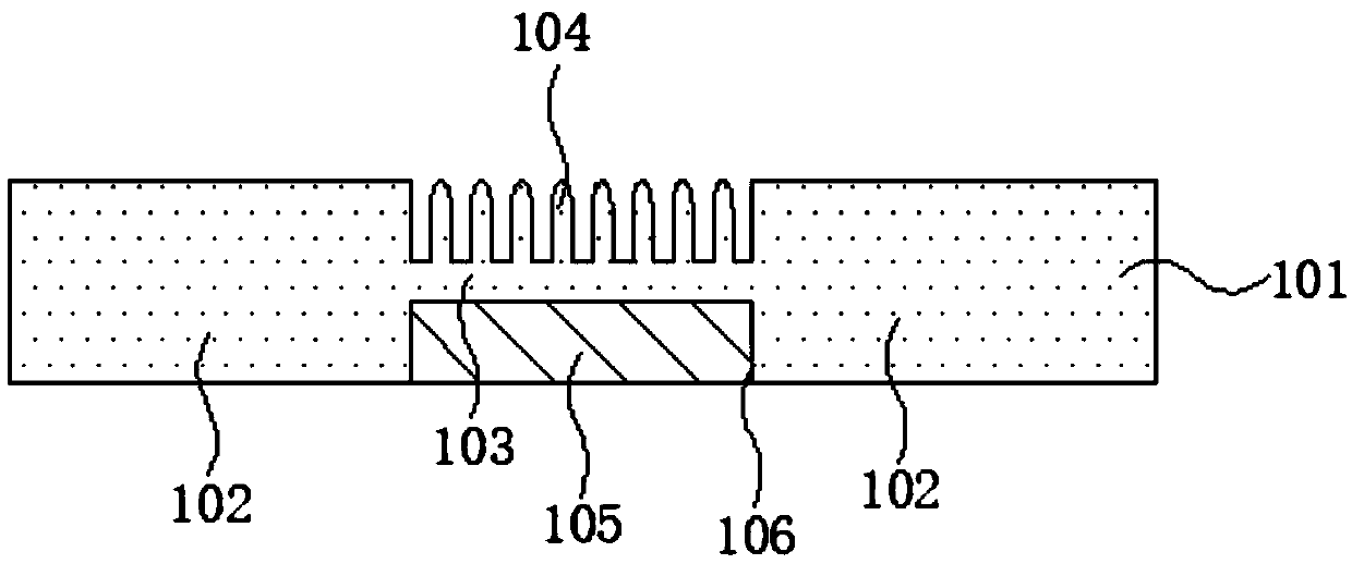
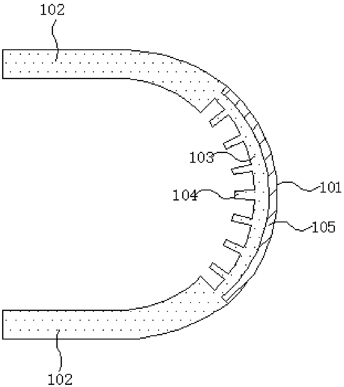
[0026] This embodiment provides a foldable backboard structure, combined below Figure 1 to Figure 2 Describe in detail.

[0027] Such as figure 1 as shown, figure 1 It is a structural schematic diagram of a foldable back panel structure provided by an embodiment of the present disclosure, wherein the foldable back panel structure includes a back panel 101, and the back panel 101 is further divided into a folding area 103 and non-folding areas located on both sides of the folding area 102. There is no interface between the folding area 103 and the non-folding area 102 to form an integral structure, so that when the foldable display device is bent, there is no obvious interface.

[0028] By selecting and modifying the material of the back plate 101, the folded area has greater deformation, and the non-folded area has higher rigidity and strength, so that there will be no folded area and non-folded area due to The phenomenon of cracking due to the existence of the interface. ...

Embodiment 2

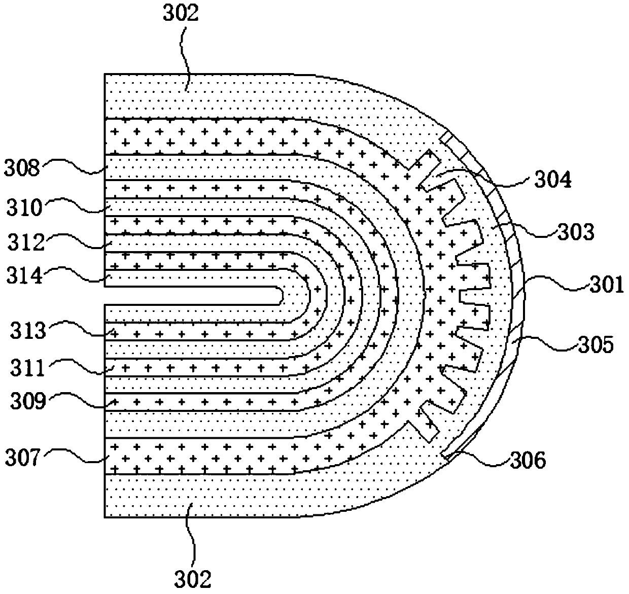
[0035] This embodiment provides a foldable display device, combined with image 3 Describe in detail.

[0036] Such as image 3 as shown, image 3 A schematic structural diagram of a foldable display device in a bent state provided in this embodiment, the foldable display device includes a back panel 301, and the back panel 301 is composed of a folding area 303 and non-folding panels located on both sides of the folding area. The folding area 303 and the non-folding area 302 form an integral structure without an interface, so that when the foldable display device is bent, there is no obvious interface.

[0037] In this embodiment, the material of the backboard can be selected from polyimide (PI). Polyimide itself has good bending resistance, stretching and high impact resistance, and can meet the needs of the backplane during production. 301 requirements for bending resistance.

[0038] Such as image 3 As shown, the folding area 303 is provided with a microstructure 304 ...


PUM


Abstract

The invention discloses a foldable backboard structure and display device. The foldable backboard structure comprises a backboard, the backboard comprises a folding area and non-folding areas which are located on the two sides of the folding area, and a micro structure is arranged on the part, close to one side of a displaying layer, of the folding area; an elastic component is included, and the elastic component is arranged on the side, away from the displaying layer, of the folding area. According to the display device, by arranging the micro structure on the side, close to the displaying layer, of the backboard folding area, the squeezing force on other membrane layers by the inner surface of the backboard is reduced in the state where a screen is folded inwards, waves are reduced, theelastic component is arranged on the side, away from the displaying layer, of the folding layer, a display screen of the foldable display device can be pulled to reach a flat state by using better deformation restoring capability of the elastic component, and the folding restoring capability of the foldable display device is enhanced.

Description

technical field [0001] The disclosure relates to the field of foldable displays, in particular to a foldable backplane structure and a display device thereof. Background technique [0002] With the continuous development of display technology, the display panel manufacturing technology is becoming more and more mature. Existing display panels mainly include Organic Light Emitting Diode (OLED), Liquid Crystal Display (LCD), A plasma display panel (Plasma Display Panel, PDP) and the like. Today, the public demand for portable devices (such as mobile phones, tablet computers, etc.) continues to increase, and foldable display devices have the characteristics of easy portability and large-size screens. [0003] The current OLED panel uses a backplane to support and protect the screen after the glass is peeled off by a laser lift-off process. During the process of folding the screen, the inner surface of the back plate is compressed and deformed, and at the same time, it also ex...

Claims


Application Information

Patent Timeline
IPC IPC(8): G09F9/30
CPCG09F9/301
Inventor 丁峰
Owner WUHAN CHINA STAR OPTOELECTRONICS SEMICON DISPLAY TECH CO LTD
Learn More