Multi-purpose double-roll continuous rheological forming device for liquid metal

A liquid metal, rheological forming technology, applied in the direction of metal rolling, can solve the problems of low cooling strength, difficult forming, small extrusion force, etc., to improve the quality of the edge, save the side sealing device, and easily squeeze The effect of press forming

Inactive Publication Date: 2010-04-07
NORTHEASTERN UNIV
View PDF0 Cites 16 Cited by
  • Summary
  • Abstract
  • Description
  • Claims
  • Application Information

AI Technical Summary

Problems solved by technology

In the continuous casting and rolling technology, there are the following technical problems: (1) The structure is complex and the control is difficult
The side seal of liquid metal requires special materials, and the structure of the side seal and shunt device is complex and difficult to control
(2) The casting and rolling speed is slow and the efficiency is low
Since the solidification and crystallization of liquid metal in the continuous casting and rolling process requires a large amount of heat to be lost in a short period of time, the high-temperature melt is mainly cooled by two rolls, which has the disadvantages of small cooling area and low cooling intensity, resulting in slow continuous casting and rolling speed and low efficiency , which is why continuous casting and rolling of steel materials cannot be applied to industrial production on a large scale
(3) The edge quality of the product is poor
But this technology still has the following problems: (1) The continuous casting and extrusion equipment adopts single-roll extrusion, and the extrusion force is small
During the process of the liquid metal from the feed port to the discharge port, the fixed shoe always has a reverse friction effect on the flow of the liquid metal, which will increase the flow resistance during the metal forming process and reduce the effective extrusion force. Seriously affect the filling of metal materials
(2) The discharge method is radial discharge, the forming resistance is large, and the types of formed metals are limited
During the casting and extrusion process, the metal has a 90° flow angle at the entrance of the extrusion die, and the metal has a large shear deformation process, which requires a large extrusion force to complete the deformation process, so metals with poor plasticity and Difficult-to-form metals cannot be formed by continuous casting and extrusion
(3) There are also great difficulties in the continuous casting and extrusion technology for forming profiles with large aspect ratios

Method used


Image

  • Multi-purpose double-roll continuous rheological forming device for liquid metal
  • Multi-purpose double-roll continuous rheological forming device for liquid metal
  • Multi-purpose double-roll continuous rheological forming device for liquid metal

Examples


Embodiment 1

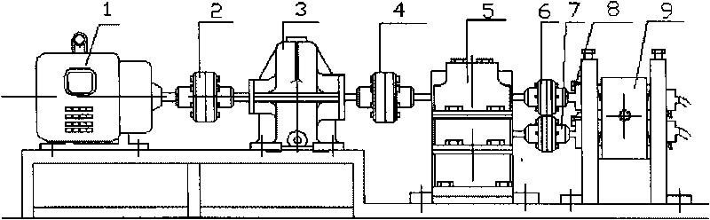
[0035] Such as figure 1 As shown, when the present invention is used for plate production, the motor 1 (DC motor) in this device is connected to one end of the reducer 3 through the half coupling I 2, and the other end of the reducer 3 is connected to the half coupling II 4 , the half-coupling II 4 is connected to one end of the gearbox 5, and the two shafts separated from the other end of the gearbox 5 are respectively connected to the main machine 9 through the half-coupling III6 and half-coupling IV7, and the two working rolls of the main machine 9 A rotational speed sensor 8 is arranged at the shaft head to measure the rotational speed.

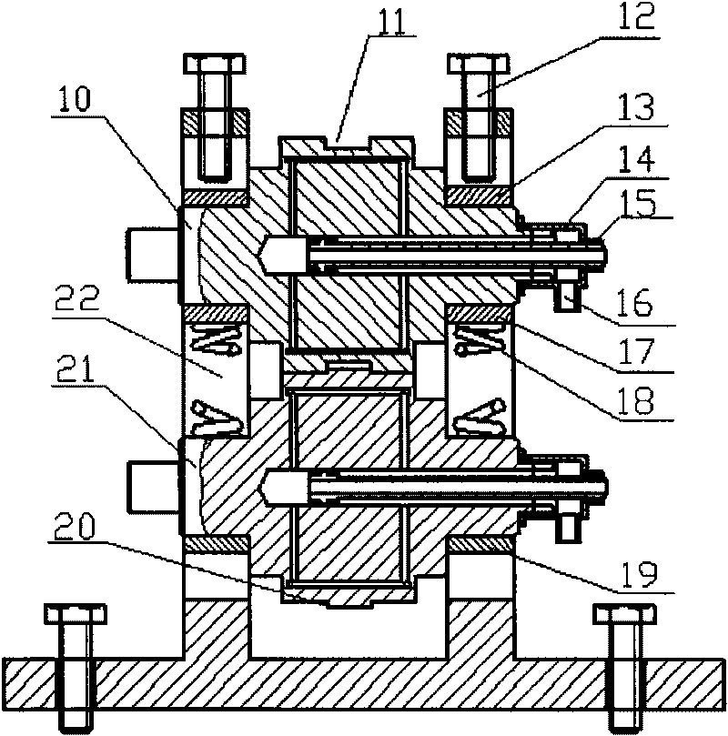
[0036] Depend on figure 2 , image 3 , Figure 4 , Figure 5 , Figure 6 As shown, the main machine 9 is mainly composed of two water-cooled work rolls that cooperate with each other. The lower work roll 21 is placed flat on the lower tile 19 placed on the two vertical plates of the frame 22, and the upper work roll 10 is placed on ...

Embodiment 2

[0042] When the present invention is used in profile production, the basic principle of host work is as follows: Figure 10 As shown, the structure of the main unit of the device along the horizontal section of the roll gap is as follows Figure 11 As shown, the difference from Example 1 is that the discharge end of the main engine is equipped with an extrusion shoe 35, and the extrusion shoe 35 has a mold cavity 40 for assembling the mold, and a mold 52 is installed in the mold cavity. Before the mold 52, there is a structure such as Figure 7 The receiving die 53 shown, the extrusion shoe cooling water hole 36 can cool the extrusion shoe. After the extrusion shoe 35 is close to the work roll under the action of the hydraulic device 54, the upper arc-shaped surface 38 of the extrusion shoe squeezes the shoe boss 37 into the groove of the upper work roll 10, and the receiving die groove 43 and the extrusion The shoe groove 42 is consistent, and the lower roller annular boss 2...


PUM

PropertyMeasurementUnit
diameteraaaaaaaaaa
widthaaaaaaaaaa
depthaaaaaaaaaa

Abstract

The invention discloses a multi-purpose double-roller continuous rheological forming device for liquid metal, which is mainly used for double-roller continuous rheological forming of plates, strips, pipes, profiles, wires, composite materials and wrapping materials. The device consists of a motor, a half coupling, a decelerator, a gear box, a main machine, a cooling water tank and a coiling machine, wherein the main machine consists of a stander, an upper working roller, a lower working roller, a feeding shoe, an extrusion shoe, a die in a cavity of the extrusion shoe, and rotating speed sensors at shaft heads of the upper working roller and the lower working roller of the main machine. An annular groove of the upper working roller is mutually matched with an annular lug boss of the lower working roller. The feeding shoe is arranged at the feeding end of the main machine, and the feeding shoe and the annular groove of the upper working roller form a feeding cavity. A metal material enters into a roller gap between the two working rollers through the feeding cavity. When producing pipes, profiles, wires and wrapping materials, the extrusion shoe is arranged at the discharging end of the main machine, and an extrusion forming die can be arranged in the cavity of the extrusion shoe. The device can realize quick continuous rheological forming of the liquid metal, and can also be used for direct forming of a semi-solid metal material.

Description

technical field [0001] The invention relates to a double-roller continuous rheological forming device for multi-purpose liquid metal used for processing plates, strips, profiles, wires, pipes, composite materials and cladding materials, belonging to the technical field of metal material forming. Background technique [0002] Metal forming plays an important role in the development of the national economy, and its development level determines the development level of social production in a certain sense. At present, metal forming mainly adopts traditional process methods, including metal smelting → casting → heating → plastic forming (forging, extrusion, rolling, drawing, etc.) The route is long, the product yield is low, the energy consumption is high, and the pollution is large. Therefore, there are problems such as high investment, high pollution, high energy consumption, and low benefit in the forming of metal materials. [0003] In order to solve problems such as envir...

Claims


Application Information

Patent Timeline
Patent Type & Authority Applications(China)
IPC IPC(8): B21B1/46B21C23/00B21C47/02
Inventor 管仁国朱立杰石路赵占勇肖召辉李江平李雪温景林
Owner NORTHEASTERN UNIV
Why Eureka
Try Eureka