
Reverse dual-powered pipe extrusion device and reverse dual-powered pipe extrusion method thereof

An extrusion method and extrusion device technology, which are applied in the field of reverse double-action pipe extrusion devices, can solve the problems of large difference in metal flow between the inner and outer layers, poor quality of the outer surface of the pipe, and uneven temperature distribution of copper ingots, etc., to achieve mold replacement Convenience and quickness, increased yield, reduced friction coefficient and frictional resistance

Active Publication Date: 2011-04-20
ZHEJIANG HAILIANG
View PDF6 Cites 15 Cited by
  • Summary
  • Abstract
  • Description
  • Claims
  • Application Information

AI Technical Summary

Problems solved by technology

The disadvantages are: there is relative movement between the ingot and the inner wall of the extrusion cylinder, and a large external friction force is generated, which causes a loss of 25% to 40% of the extrusion force and increases energy consumption; the temperature distribution of the copper ingot is uneven, and the inner and outer metal flows The difference is large, which leads to serious defects such as shrinkage and delamination of extruded pipes. Copper pipes with shrinkage and delamination defects can only be scrapped and returned to the furnace, which greatly reduces the yield of finished products and significantly increases energy consumption and cost.
However, the current reverse extrusion devices mostly use single-action extrusion, that is, only the extrusion shaft produces extrusion movement during the entire extrusion process, which determines that this type of extrusion device and its extrusion method are only suitable for producing single, Oversized products, and the quality of the outer surface of the pipe is poor, and the production efficiency is low

Method used


Image

  • Reverse dual-powered pipe extrusion device and reverse dual-powered pipe extrusion method thereof
  • Reverse dual-powered pipe extrusion device and reverse dual-powered pipe extrusion method thereof
  • Reverse dual-powered pipe extrusion device and reverse dual-powered pipe extrusion method thereof

Examples


Embodiment Construction

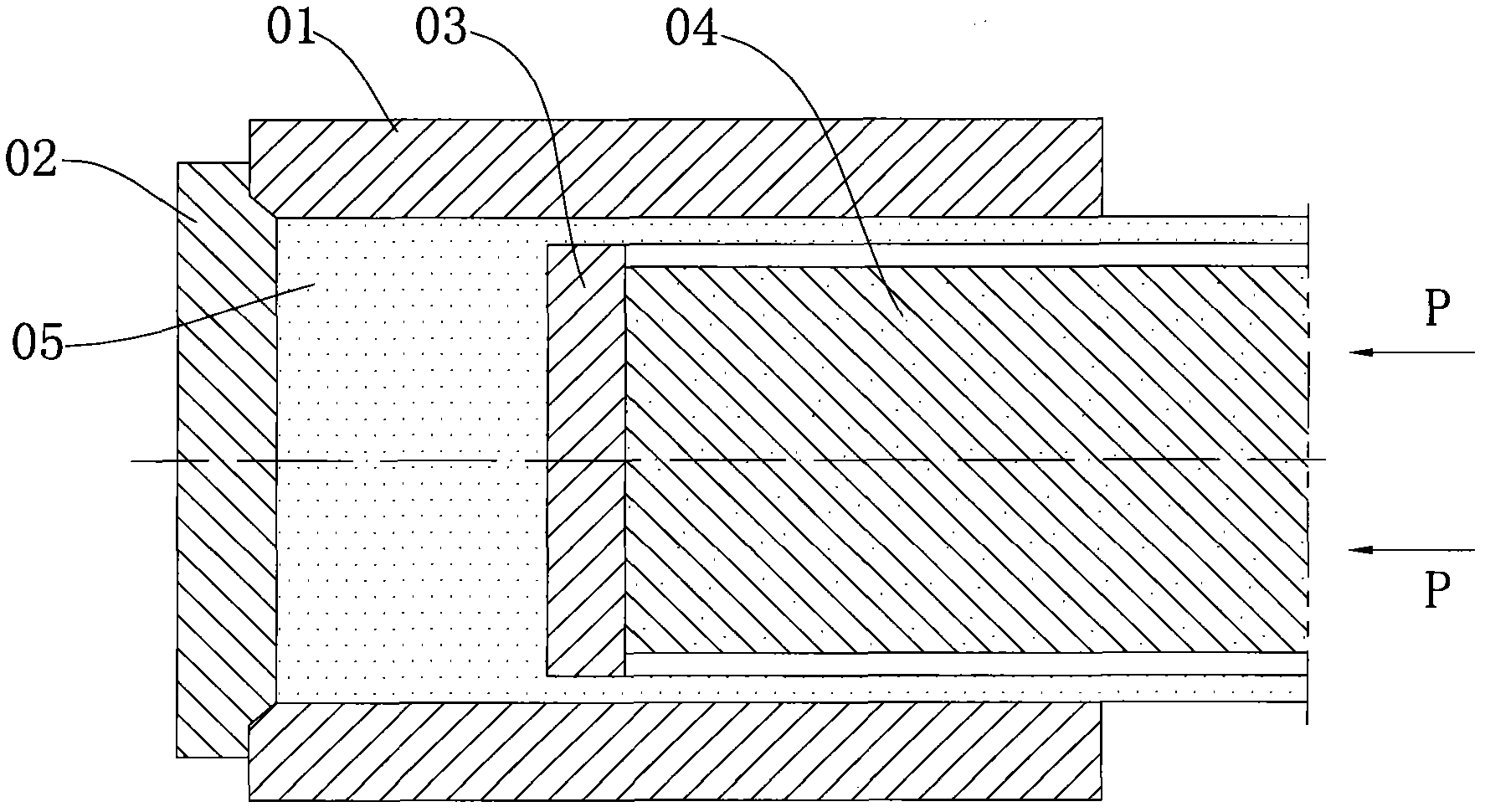
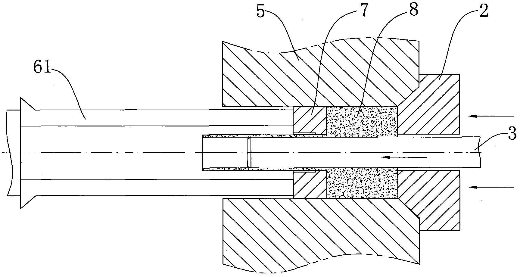
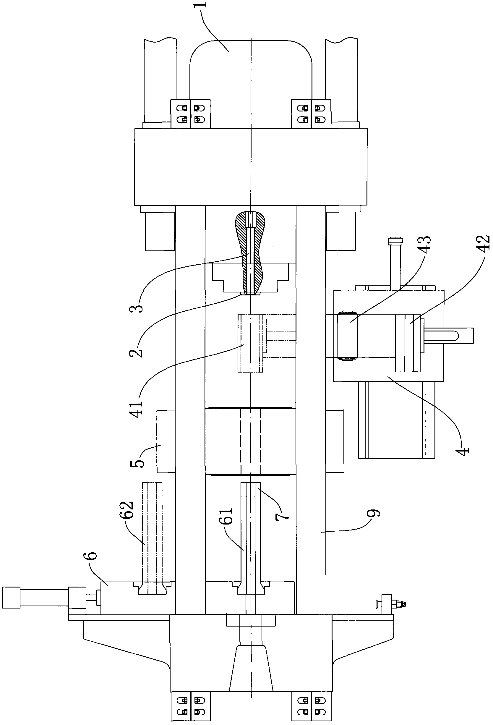
[0032] Such as image 3 As shown, the reverse double-action pipe extrusion device includes frame slide rail 9, extrusion main cylinder 1 with extrusion plug 2, extrusion cylinder 5, and movable die base 6 with extrusion die shaft 61 , the extrusion master cylinder 1, the extrusion barrel 5, and the mobile mold base 6 are sequentially arranged on the frame slide rail 9 and can move axially along the frame slide rail 9; the extrusion master cylinder 1 is provided with a perforation Cylinder, perforating needle 3 is installed on the perforating cylinder, extrusion die shaft 61 is provided with extrusion die 7 corresponding to one end of extrusion cylinder 5; perforating cylinder drives perforating needle 3 to pass through from the center of extrusion plug 2 to push the billet into extrusion The ingot is pierced in the pressing cylinder 5; during the extrusion process, the extrusion plug 2 is driven by the extrusion master cylinder 1 to push the extrusion cylinder 5 and the ingot ...


PUM


Abstract

The invention discloses a reverse dual-powered pipe extrusion device and a reverse dual-powered pipe extrusion method thereof, the extrusion device comprises a frame sliding rail, a main extrusion cylinder having an extrusion choke plug, an extruding container and a moving die holder having an extrusion die shaft, the main extrusion cylinder, the extruding container and the moving die holder are orderly installed on the frame sliding rail and can axially move along the same; the main extrusion cylinder is internally provided with a punching tank on which punching needles are installed, one end of the extrusion die shaft corresponding to the extruding container is provided with an extrusion die, the punching tank drives the punching needles to penetrate out from the centre of the extrusionchoke plug so as to push an ingot blank out of the extruding container and finish ingot blank punching; in an extrusion process, under the driving of the main extrusion cylinder, the extrusion choke plug pushes the extruding container and the ingot blank to move towards the extrusion die, the punching needles and the extruding container moves synchronously, and the extrusion choke plug is matchedwith the extrusion die to implement reverse extrusion of the ingot blank in the extrusion container; compared with a traditional single-powered extrusion device, the reverse dual-powered pipe extrusion device of the invention has the advantages of high flexibility and convenient and quick die exchange process.

Description

technical field [0001] The invention belongs to the technical field of pipe extruding, and in particular relates to a reverse double-action pipe extruding device and an extruding method thereof. Background technique [0002] Copper, copper alloy and other non-ferrous metal alloy pipes are mainly produced by extruder extrusion, and the extruder extrusion method is divided into forward extrusion and reverse extrusion. [0003] The working principle of forward extrusion is: during the extrusion process, the extrusion cylinder and the extrusion die are fixed, and the hydraulic cylinder acts on the extrusion shaft, perforation needle, and extrusion pad to overcome the effect on the inner wall of the extrusion cylinder and the perforation. The friction force of the needle, the surface of the compression cone in the denatured area, the surface of the sizing area of ​​the extrusion die, and the plastic deformation resistance of the metal push the billet to move toward the extrusion ...

Claims


Application Information

Patent Timeline
Patent Type & Authority Applications(China)
IPC IPC(8): B21C23/20B21C35/04
Inventor 赵学龙狄大江黄登科马为民黄路稠楼娜刘永刘美
Owner ZHEJIANG HAILIANG
Learn More