
Vacuum magnetic transmission mechanism

A technology of magnetic transmission and magnetic transmission, applied in the direction of permanent magnet clutch/brake, etc., can solve the problems of shortening the service life of the transmission mechanism, affecting the cleanliness of products, transmission energy consumption, etc., to improve the cleanliness, and the layout of the structure is compact and reasonable. , The effect of low transmission energy consumption

Inactive Publication Date: 2011-08-31
DONGGUAN ANWELL DIGITAL MASCH CO LTD
View PDF0 Cites 0 Cited by
  • Summary
  • Abstract
  • Description
  • Claims
  • Application Information

AI Technical Summary

Problems solved by technology

Since most of the above-mentioned transmission methods adopt the direct contact transmission mode in which the gears mesh with each other, it is easy to cause mechanical wear during the transmission process, resulting in transmission energy consumption; Contact, it is easy to granulate the moving components of the transmission mechanism due to friction, and the dust generated enters the vacuum chamber with the mechanical mechanism, which affects the cleanliness of the product and generates a lot of noise during the transmission process; in addition, each movement Friction between components shortens transmission life

Method used


Image

  • Vacuum magnetic transmission mechanism
  • Vacuum magnetic transmission mechanism

Examples


Embodiment Construction

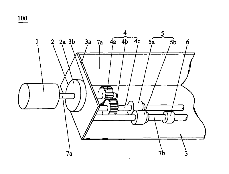
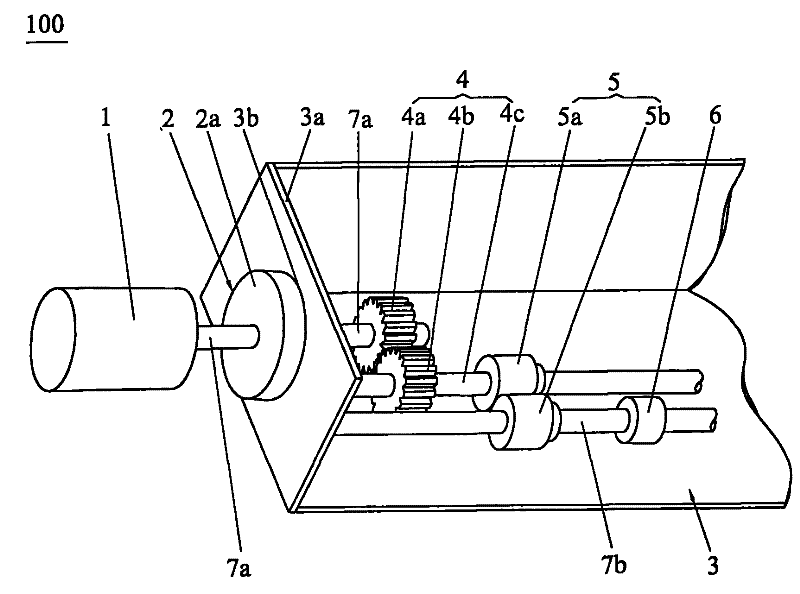
[0013] Such as figure 1 As shown, the vacuum magnetic transmission mechanism 100 of the present invention includes a driving device 1, a driving shaft 7a, a transmission shaft 4c, a driven shaft 7b, a magnetic fluid transmission device 2, a gear transmission device 4 and a magnetic force transmission device 5. The device 2 is installed on the chamber wall 3a of the vacuum chamber 3 and is located outside the vacuum chamber 3, one end of the driving shaft 7a is fixedly connected with the driving device 1, and the other end of the driving shaft 7a passes through the The magnetic fluid transmission device 2 extends into the vacuum chamber 3 and is connected with one end of the gear transmission device 4, the other end of the gear transmission device 4 is connected with one end of the magnetic force transmission device 5, and the magnetic force transmission device The other end of 5 is fixedly connected with the driven shaft 7b, and the driven shaft 7b is connected with the mechan...


PUM


Abstract

The invention discloses a vacuum magnetic transmission mechanism which is suitable for driving a mechanical mechanism in a vacuum chamber to rotate, comprising a driving device, a driving shaft, a driven shaft, a magnetic fluid transmission device, a gear transmission device and a magnetic force transmission device, wherein, the magnetic fluid transmission device is positioned outside the vacuum chamber; the driving shaft passes through the magnetic fluid transmission device and extends into the vacuum chamber to be connected with the gear transmission device which is connected with the magnetic force transmission device; the magnetic force transmission device is fixedly connected with the driven shaft which is connected with the mechanical mechanism in the vacuum chamber; the gear transmission device is composed of a plurality of adjacent gears which are mutually meshed; the driving device drives the gear of the gear transmission device to rotate, the rotation of the gear drives a magnetic force driving wheel to rotate, and the magnetic force driving wheel drives the mechanical mechanism to rotate. The invention has small driving energy consumption, high clean degree, super silence, convenient installation and simple and compact structure.

Description

technical field [0001] The invention relates to a transmission mechanism for power transmission in the vacuum environment industry, in particular to a vacuum magnetic transmission mechanism for providing rotational power to a mechanical mechanism in a vacuum chamber on an organic light emitting diode production line. Background technique [0002] With the continuous development of the economy, the continuous advancement of science and technology and the decrease of world energy, people pay more and more attention to energy conservation and utilization efficiency in production, so that the harmonious development of man and nature can meet the requirements of China's new industrialization road. [0003] For example, in the display industry of digital products that require a very high vacuum environment, in order to save energy and reduce production costs, enterprises have increased investment in research and development, and are constantly pursuing new energy-saving products. ...

Claims


Application Information

Patent Timeline
Patent Type & Authority Patents(China)
IPC IPC(8): H02K49/10
Inventor 杨明生范继良郭业祥王曼媛王勇
Owner DONGGUAN ANWELL DIGITAL MASCH CO LTD
Learn More