Supercharge Your Innovation With Domain-Expert AI Agents!

Illumination system and display device

一种照明系统、显示器的技术,应用在照明系统领域,能够解决亮度差等问题,达到改善均匀性、均匀光分布的效果

Inactive Publication Date: 2010-01-20
KONINK PHILIPS ELECTRONICS NV
View PDF9 Cites 7 Cited by
  • Summary
  • Abstract
  • Description
  • Claims
  • Application Information

AI Technical Summary

Problems solved by technology

[0006] A disadvantage of known lighting systems is that reflective optics typically cause brightness differences in segmented areas

Method used


Image

  • Illumination system and display device
  • Illumination system and display device
  • Illumination system and display device

Examples


Embodiment Construction

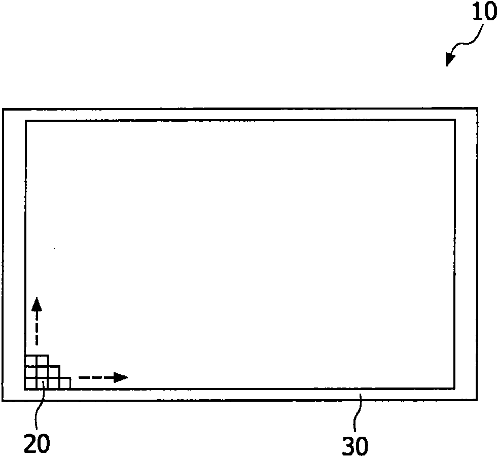
[0037] Figure 1A is a schematic front view of a display device 10 according to the present invention. The display device 10 includes an illumination system 30 and a display 20 . The lighting system 30 is arranged to illuminate the display 20 . The display 20 is, for example, a known non-emissive display comprising a plurality of pixels (represented by a square array). Each pixel is arranged to control the transmission of light emitted by the light source through that pixel, and thereby control the brightness emitted by the pixel. Selecting the transmittance of different pixels enables an image to be displayed on the display 20 . A pixel typically includes a plurality of sub-pixels (not shown) with different color filters (not shown), and likewise they control the transmission of light of a predetermined color and thus enable a colored image to be displayed on the display 20 .

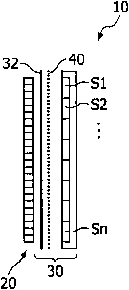
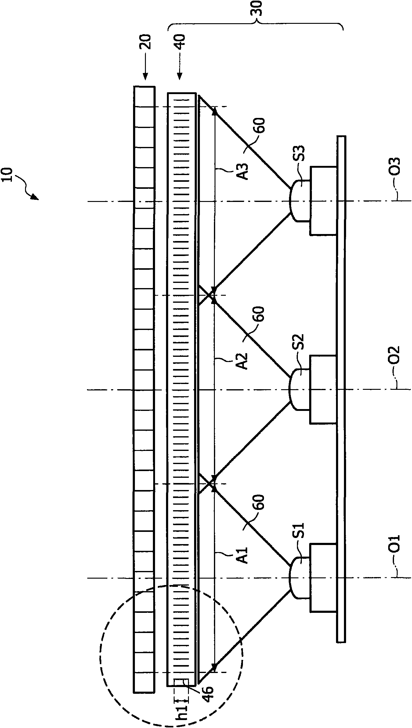
[0038] Figure 1B is a schematic cross-sectional view of a display device 10 according to the p...


PUM


Abstract

The invention relates to an illumination system (30) for illuminating a display (20) of a display device (10), and to a display device. The illumination system comprises a light source (S1, S2, S3) and an optical control layer (40). The light source emits light via the optical control layer to the display for illuminating a predefined area (A1, A2, A3) on the display. The light is emitted from the light source in a diverging beam in a particular direction (O1, O2, O3) towards the predefined area. The optical control layer comprises an arrangement of portions (46) having a refractive index which is different from the optical control layer. The portions are arranged to reflect a part of the diverging light towards the predefined area. The measures according to the invention have the effect that the arrangement of portions in the optical control layer confines both the light emitted by the light source and the backscattered light reflected back to the light source to substantially within the predefined area.

Description

technical field [0001] The invention relates to a lighting system for illuminating a display. [0002] The invention also relates to a display device. Background technique [0003] Illumination systems for illuminating display devices are known per se. The illumination system is used in particular as a backlight system in non-emissive displays, such as liquid crystal display devices, also called LCD panels, which are used eg in television receivers, (computer) monitors, (cordless) telephones and PDAs. These lighting systems can also be used, for example, in projection systems, such as digital projectors, also called beamers, for projecting images or displaying television programmes, films, video programs or DVDs or the like. [0004] In order to reduce motion blur in display devices, known lighting systems include an array of light sources, which can be operated in a scanning backlight mode of operation. In order to implement a scanning backlight mode, the array of light ...

Claims


Application Information

Patent Timeline
Patent Type & Authority Applications(China)
IPC IPC(8): F21V7/00F21V5/00
CPCG02F1/133606G02B6/0053Y10S362/80
Inventor F·皮尔曼G·森尼尼
Owner KONINK PHILIPS ELECTRONICS NV
Features
  • R&D
  • Intellectual Property
  • Life Sciences
  • Materials
  • Tech Scout
  • Unparalleled Data Quality
  • Higher Quality Content
  • 60% Fewer Hallucinations
Learn More