Vibrating tactile interface

A kind of interface and tactile technology, applied in the direction of instrument, electrical digital data processing, user/computer interaction input/output, etc., can solve the problems of large volume and limited detection area

Active Publication Date: 2012-04-04
UNIV DES SCI & TECH DE LILLE
View PDF2 Cites 3 Cited by
  • Summary
  • Abstract
  • Description
  • Claims
  • Application Information

AI Technical Summary

Problems solved by technology

However, on the one hand, this type of interface is very bulky; on the other hand, the dimension of the contact surface (the width of the ring) in the direction perpendicular to the direction of wave propagation is necessarily small, thus disadvantageously limiting the area that can be probed by the user's finger. area

Method used


Image

  • Vibrating tactile interface
  • Vibrating tactile interface
  • Vibrating tactile interface

Examples


Embodiment

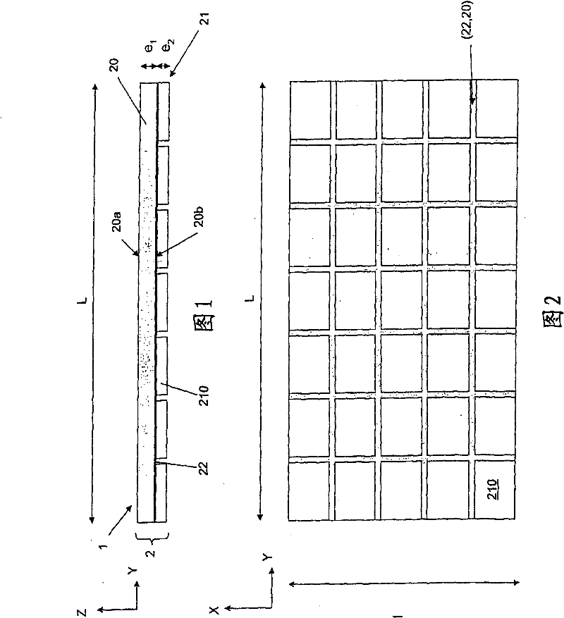
[0059] In a specific embodiment given only as an indication, the resonant base 20 is a thickness (e 1 ) equal to 2mm, length L equal to 83mm, width (I) equal to 49mm beryllium copper plate. Each piezoelectric ceramic element 210 is a 11mm * 9mm, thickness (e 2 ) is equal to a rectangular plate of 1 mm. These piezoelectric ceramic elements 210 are fixed on the board 20 with epoxy glue. The frequency f of the intrinsic bending mode along the propagation axis Y Y is 30.5kHz; the frequency f of the intrinsic bending mode along the propagation axis X X 44.8kHz.

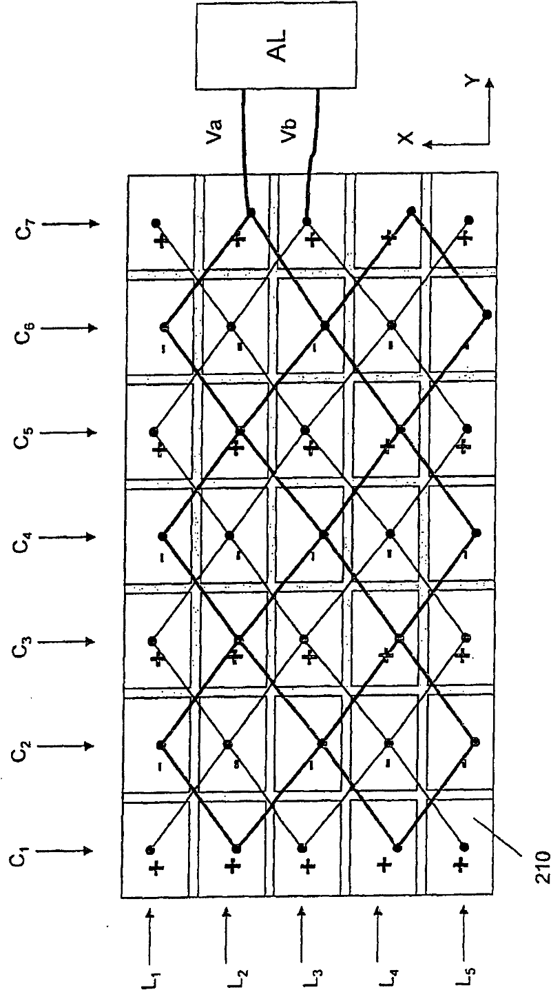
[0060] Bending mode along length L (axis Y) / Figure 6

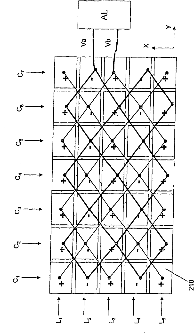
[0061] Figure 6 An example of deformation of the contact surface 20a of the interface 1 along the longitudinal propagation axis Y is shown. The deformation is measured point by point by a laser vibrometer. To obtain this deformation, the signal V a and V b Has the following characteristics:

[0062] V a = V1.sin(ωt), V b =V1.sin(ωt-π)

[0063] Exci...


PUM


Abstract

The tactile interface (1) comprises a vibrating structure (2) with a plate (20) one (20a) face of which forms said vibrating contact surface of the interface and a piezoelectric layer (21) fixed to the other face of said plate, said structure having at least one flexing mode, characterised by a resonance frequency between 10kHz and 100kHz and electrical supply means (AL) connected to the piezoelectric layer (21). The piezoelectric layer (21) and the electrical supply means (AL) are designed to stimulate the flexing mode of the vibrating structure (2) and to generate stationary Lamb waves in the vibrating structure (2) with a propagation direction following at least one rectilinear propagation axis. The tactile interface permits the tactile reproduction of fine textures or roughness by altering the tactile sensation of touching the contact surface (20a) and modulating the 'Squeeze film' effect.

Description

technical field [0001] The present invention relates to a new tactile interface using a vibrating surface (preferably ultrasonic) and making it possible to obtain a squeeze film effect. By modulating the extruded film effect, the interface can tactilely reproduce very fine textures (textures) or roughness. Background technique [0002] In order to dynamically reproduce very fine textures or roughnesses that can be perceived by touch, it is known hitherto to construct a tactile interface comprising a vibrating contact surface and means for generating vibrations to Ultrasonic mechanical vibrations with small amplitudes are produced. [0003] Typically, the mechanical vibration of the contact surface of such ultrasonic tactile interfaces is generated by surface waves called Rayleigh or by Lamb waves, as the case may be. [0004] Rayleigh wave or surface wave (SAW) transducers [0005] On the surface of a semi-infinite isotropic medium, a two-component surface wave called Ra...

Claims


Application Information

Patent Timeline
Patent Type & Authority Patents(China)
IPC IPC(8): G06F3/01
CPCG06F3/016G06F3/162
Inventor M·比耶F·吉罗B·勒迈尔塞马伊
Owner UNIV DES SCI & TECH DE LILLE
Why Eureka
Try Eureka