Non-contact rotary power transfer system

A technology of power transmission and power inversion, which is used in the conversion of AC power input to DC power output, radiation diagnosis data transmission, and output power conversion devices, etc.

Active Publication Date: 2010-01-20
ANLOGIC CORP (US)
View PDF0 Cites 20 Cited by
  • Summary
  • Abstract
  • Description
  • Claims
  • Application Information

AI Technical Summary

Problems solved by technology

Increased power may require more puck space for increased duct c

Method used


Image

  • Non-contact rotary power transfer system
  • Non-contact rotary power transfer system
  • Non-contact rotary power transfer system

Examples


Embodiment Construction

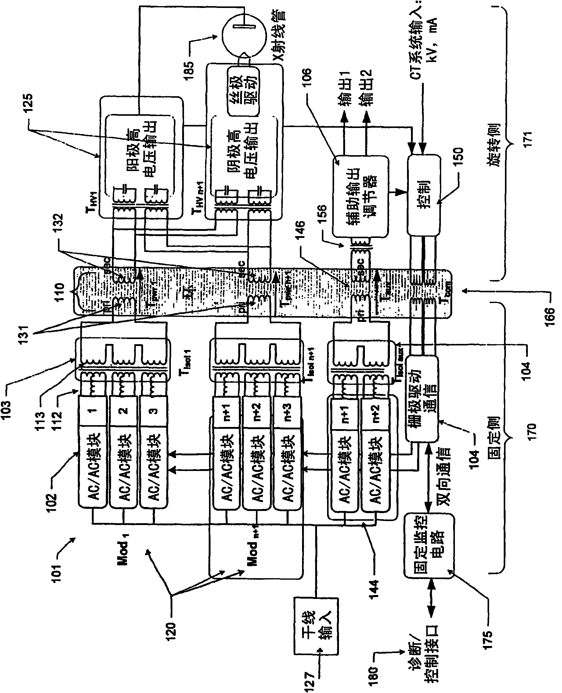
[0023] Systems and methods are described that increase the available space on a rotating gantry by relocating high voltage, high power inverters and auxiliary power supplies to a fixed frame, without physical contact (such as brushes) Power is delivered to the rotating system under high conditions and at high speeds (eg, greater than about 300 RPM). Specifically, a resolver is described that couples power between a stationary side and a rotating side. Isolation and decoupling of the mains supply is achieved by an isolation and summing transformer driving the primary winding of the resolver in a multi-phase configuration. Applications in which the contactless power delivery system described in this disclosure may be used include, but are not limited to, CT (Computed Tomography) systems.

[0024] figure 1 A contactless power transfer system 100 according to one embodiment of the present disclosure is shown. although figure 1 The example shown in can be used as Figure 11 Th...


PUM


Abstract

A power delivery system includes a rotary transformer having a primary winding and a secondary winding and configured to transfer power between stationary coupling elements on a stationary side and rotational coupling elements on a rotational side. The rotational coupling elements share a central axis with the stationary coupling elements, and are adapted to rotate with respect to the stationary coupling elements. The power delivery system includes an isolation transformer that drives the primary winding of the rotary transformer, and a plurality of power inverter stages whose outputs are adapted to be summed and coupled to the rotary transformer. A plurality of output power converters receive transmitted power from the rotary transformer. A plurality of control elements, disposed on the rotating side, are configured to close a feedback loop on desired and actual performance of the output power converters, and to control the power inverter stages.

Description

[0001] Cross-references to related applications [0002] This application is filed under 35 U.S.C. § 119(e) on December 20, 2006, entitled "Isolated Modular, Multi-Channel, and Multi-Phase Non-Contacting Rotary Power Transfer System," Serial No. 60 / 876,055 Priority of a decided, co-owned U.S. provisional patent application. Background technology [0004] Next generation medical computed tomography (CT) equipment may have to address increased demands on modes of operation and reduced patient dose. Modalities such as real-time cardiac imaging may require faster rotational speeds, and high voltages that respond to higher peak power. Power increases may require more puck space for increased tube cooling and more space for traditional high voltage power supplies. It is desirable to provide solutions to these problems without imposing too many constraints on CT design. The need for reliable performance at higher speeds and power requires a new approach to rotary high-voltage powe...

Claims


Application Information

Patent Timeline
IPC IPC(8): H01F38/18
CPCA61B6/56H01F38/18H02J5/005H01F2038/143H01F2038/146H02J50/12H02J50/70H02J50/40H02J2310/23H05G1/10H02J50/80A61B6/035H02M7/53871
Inventor A·C·德尔福奇
Owner ANLOGIC CORP (US)
Why Eureka
Try Eureka