
Optical fiber drawing heating furnace

A heating furnace and optical fiber technology, applied in the field of optical fiber production, can solve the problems of uneven size control and low manufacturing efficiency, and achieve the effect of ensuring stability and size control

Inactive Publication Date: 2010-01-27
JIANGSU HENGTONG PHOTOELECTRIC
View PDF0 Cites 2 Cited by
  • Summary
  • Abstract
  • Description
  • Claims
  • Application Information

AI Technical Summary

Problems solved by technology

The drawing of quartz optical fiber generally adopts the method of heating the heating furnace as a whole, and the method of plastic optical fiber is generally adopted at present, but this method has problems such as low manufacturing efficiency and uneven size control for the realization of plastic optical fiber.

Method used


Image

  • Optical fiber drawing heating furnace
  • Optical fiber drawing heating furnace
  • Optical fiber drawing heating furnace

Examples


Embodiment Construction

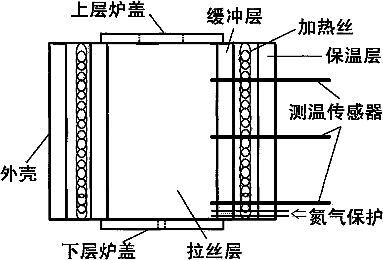
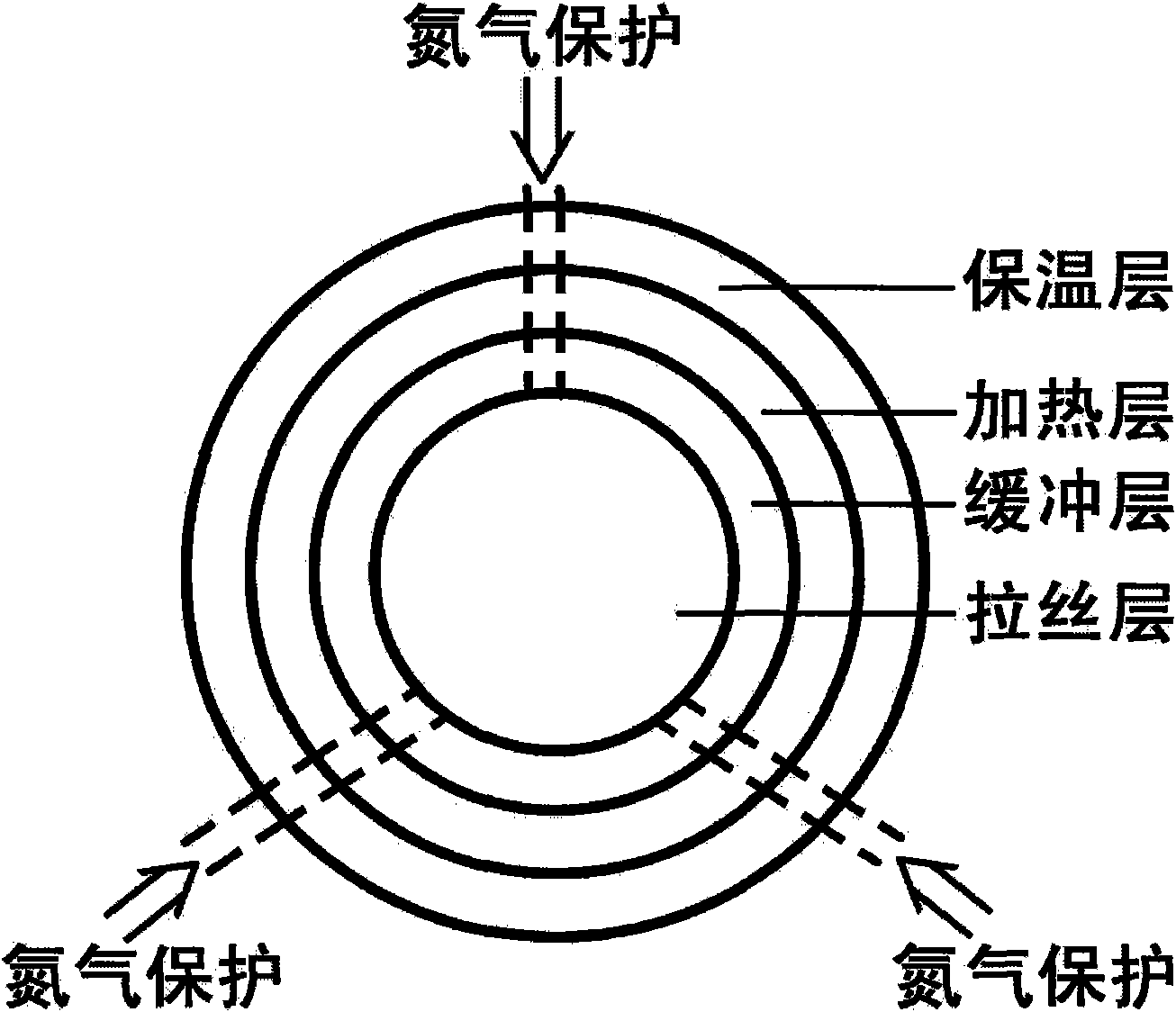
[0019] figure 1 The overall structure of the optical fiber heating furnace of the present invention is shown. The heating furnace is generally a cylindrical structure, which is divided into 5 layers from outside to inside: outer shell, insulation layer, heating wire, buffer layer, and wire drawing layer. And equipped with three sets of temperature sensors, three sets of protective gas ventilation devices ( figure 1 , figure 2 The position pointed to by "nitrogen protection" in the middle), and the upper and lower furnace covers. Among them, three sets of temperature sensors are perpendicular to the above-mentioned 5 layers (i.e. shell, insulation layer, heating wire, buffer layer, drawing layer), that is, perpendicular to the central axis of the cylindrical structure, and run through the above-mentioned 5 layers (i.e. inserted from the shell, until inserted into the brushed layer). Among them, the three sets of protective gas ventilation devices are also perpendicular to t...


PUM

PropertyMeasurementUnit
Thicknessaaaaaaaaaa

Abstract

The invention relates to an optical fiber drawing heating furnace capable of heating with a gradient temperature section. The overall heating furnace is in a cylinder structure, and is divided into five layers from internal to external, including a shell, a heat insulating layer, heating wires, a buffering layer and a fiber drawing layer. The heating furnace is provided with three sets of temperature sensors, three sets of protective aeration devices, an upper furnace cover and a lower furnace cover. The optical fiber drawing heating furnace greatly ensures the stability and the dimension control of the optical fiber forming by using a special heating design of the furnace body so as to provide an ideal proposal for developing small-sized plastic optical fibers for communications.

Description

technical field [0001] The invention relates to the field of optical fiber production, in particular to a structural design of an optical fiber drawing heating furnace. Background technique [0002] The existing heating furnace for optical fiber drawing generally adopts overall heating without temperature section setting, and the design has certain disadvantages, and cannot meet the drawing requirements of some special materials. Nowadays, optical fibers are generally divided into two categories, one is silica optical fiber, the other is plastic optical fiber. The composition of quartz optical fiber is relatively simple, while there are many varieties of plastic optical fiber, such as PP, PE, PC, PMMA, PVC, PBT and so on. The drawing of quartz optical fiber generally adopts the method of heating the whole heating furnace, and the method of plastic optical fiber is generally adopted at present, but this method has problems such as low manufacturing efficiency and uneven size ...

Claims


Application Information

Patent Timeline
IPC IPC(8): B29C55/00
Inventor 周春东王学忠马建林孙春权顾利国
Owner JIANGSU HENGTONG PHOTOELECTRIC
Learn More