
Rear part structure of vehicle body

A technology for the rear of the body and the body, which is applied to the superstructure, the sub-assembly of the superstructure, the vehicle parts, etc., can solve the problems such as the expansion of the luggage space and the compression of the luggage space, etc., and achieve efficient absorption and improvement. Energy absorption performance, the effect of high-efficiency collision energy

Inactive Publication Date: 2010-01-27
HONDA MOTOR CO LTD
View PDF3 Cites 13 Cited by
  • Summary
  • Abstract
  • Description
  • Claims
  • Application Information

AI Technical Summary

Problems solved by technology

Therefore, in the conventional vehicle body rear structure, the trunk space and the space in the vehicle interior are compressed due to the increase in the cross section of the rear frame, and it is difficult to expand the trunk space and the space in the vehicle interior.

Method used


Image

  • Rear part structure of vehicle body
  • Rear part structure of vehicle body
  • Rear part structure of vehicle body

Examples


no. 3 approach

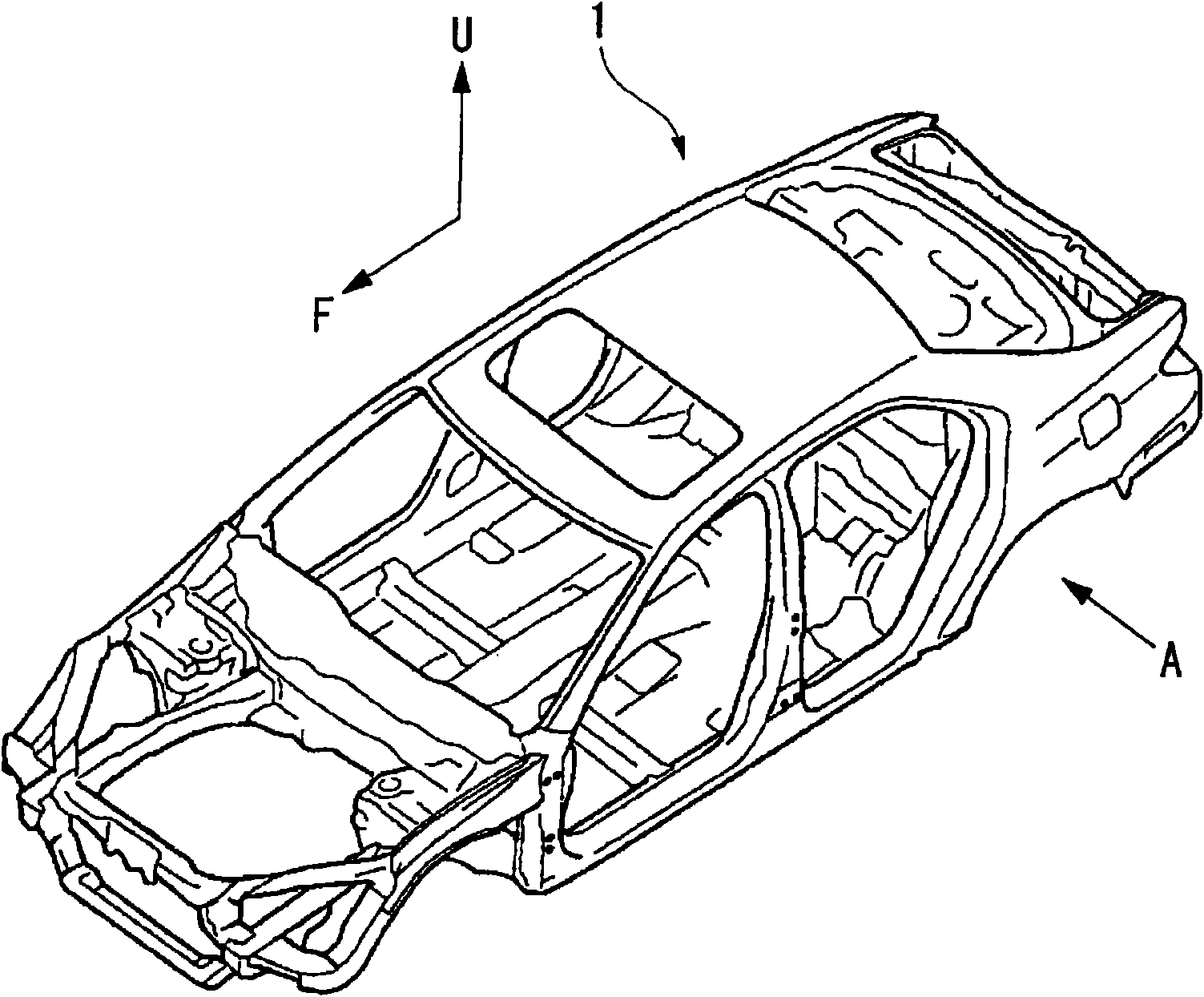
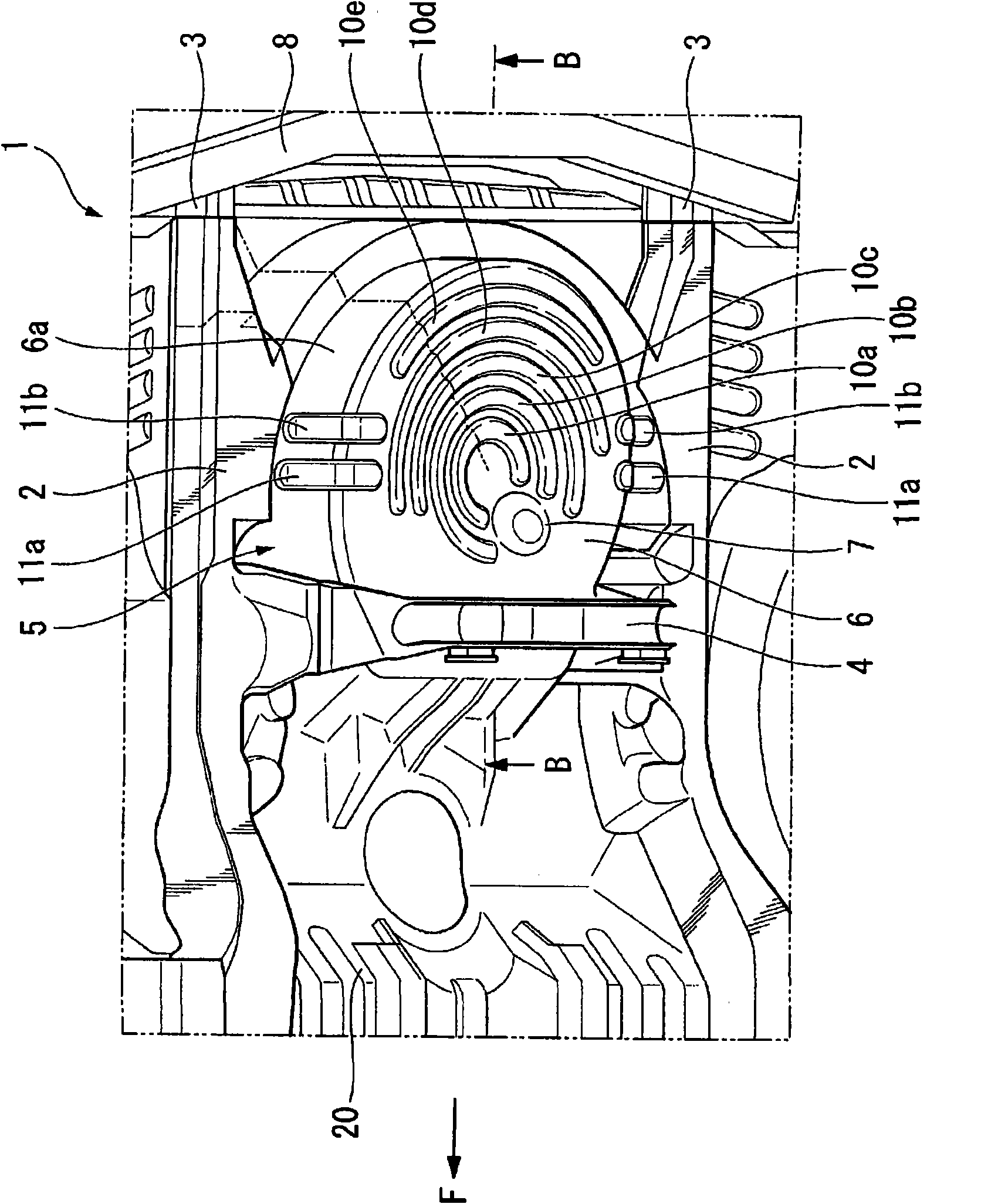
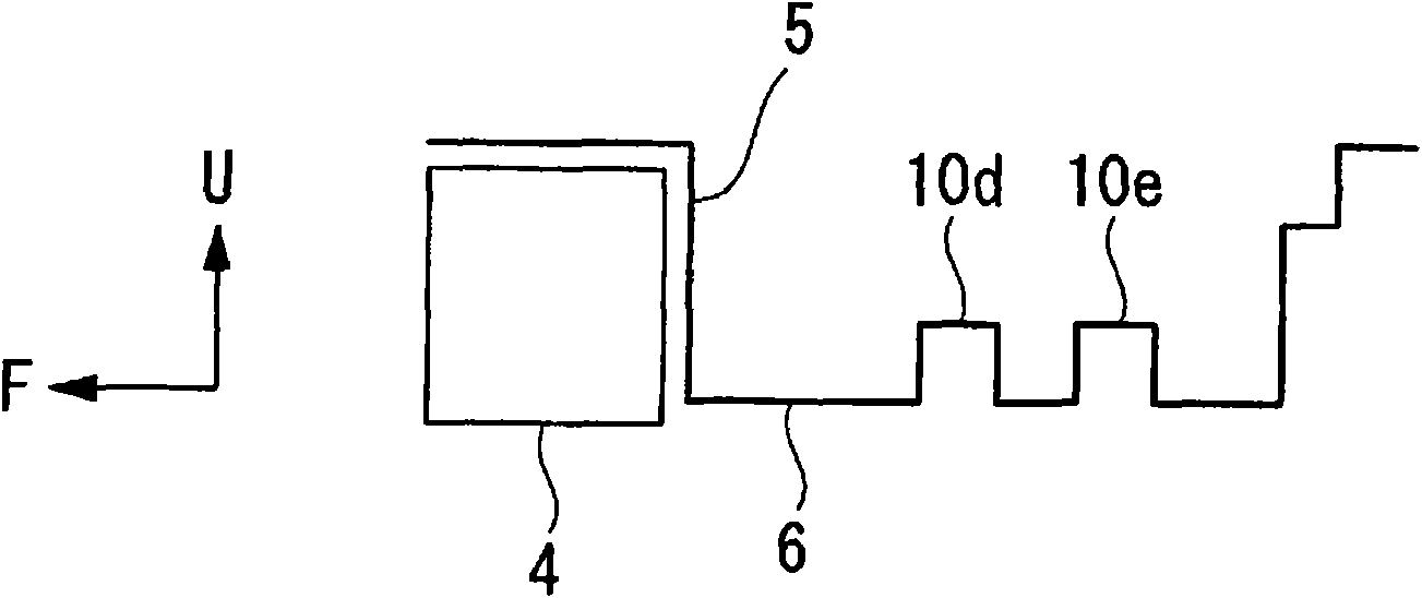
[0075] Figure 8 It is a perspective view of a vehicle 201 to which the rear structure of the vehicle body of the present invention is applied, viewed obliquely from above. Figure 9 is along the vehicle 201 Figure 8 Sectional view of line C-C. Figure 10 is along Figure 8 A sectional view of the vehicle 201 on line D-D.

[0076] In the vehicle 201, a pair of left and right rear frames 202 are arranged on the lower surface of the rear portion of the vehicle body substantially along the front-rear direction of the vehicle body. The front ends of both rear frames 202 are joined to the center cross member 204 between the left and right side sills 203 of the vehicle body and the rear ends of the side sills 203 . A rear cross member 205 is erected substantially in the middle of both rear frames 202 , and a rear panel 206 forming a rear wall of the vehicle body is joined to rear ends of both rear frames 202 . A bumper beam (not shown) of a rear bumper is disposed on the vehic...


PUM


Abstract

In a rear structure of a vehicle body, a spare tire pan (5) is supported on a pair of rear frames (2, 2) extending in substantially longitudinal direction of a vehicle body. To enhance absorption of energy at the time of collision on the side without increasing the cross sectional areas of the rear frames, arcuate beads (10a-10e) continuous in a circular arc shape are formed on the spare tire pan (5). The arcuate beads (10a-10e) are so arranged as to project to rearward of the rear of the vehicle body and to be separated from each other at predetermined pitches.

Description

technical field [0001] The present invention relates to a vehicle body rear structure capable of improving the energy absorption performance of a vehicle in a rear collision. [0002] This application claims priority based on Japanese Patent Application No. 2007-093922 filed on March 30, 2007 and Japanese Patent Application No. 2007-123384 filed on May 8, 2007, and the contents thereof are incorporated herein. Background technique [0003] At the rear of the vehicle, a pair of left and right rear frames extending substantially in the front-rear direction of the vehicle body are provided. The rear frame functions to ensure the rigidity of the vehicle body and to absorb energy in a rear collision. The rear frame functions as a skeleton member of the rear part of the vehicle body, and is crushed in the longitudinal direction during a rear collision, thereby efficiently absorbing collision energy. [0004] A structure is known in which both edges of a spare tire disc to which ...

Claims


Application Information

Patent Timeline
IPC IPC(8): B62D25/20B62D43/10
Inventor 安原重人江川泰久松浦裕志
Owner HONDA MOTOR CO LTD
Learn More