Self-controlled device for valve

A technology of automatic control devices and valves, which is applied in the direction of valve devices, safety valves, balance valves, etc., can solve the problems of ineffective quantitative restrictions on water and gas consumption, and achieve the effect of simple structure

Inactive Publication Date: 2010-02-03
孙寿田
View PDF0 Cites 8 Cited by
  • Summary
  • Abstract
  • Description
  • Claims
  • Application Information

AI Technical Summary

Problems solved by technology

[0002] At present, there are many types of water-saving and gas-saving devices on the market, but these products generally save water and gas to a certain extent, but the effect of quantitative restrictions on water and gas is not obvious

Method used


Image

  • Self-controlled device for valve

Examples


Embodiment Construction

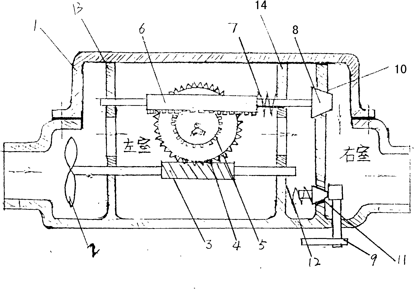
[0008] from figure 1 It can be seen that a valve automatic control device of the present invention is composed of a casing 1, a partition 10, an impeller 2, a linkage rod, a worm 3, a reverse ratchet device, a rack 6, a spring, a piston, and a rescue device. Among them, the casing 1 is divided into two left and right chambers which are not connected with each other by the partitions with holes 10, 13, 14. The impeller 2 is connected with the worm 3 through the partition 13 of the left chamber through the linkage rod. The reverse ratchet device consists of two Composed of coaxial reverse ratchets 4 and 5, the reverse ratchet 4 bar meshes with the thread on the worm 3, the reverse ratchet 5 meshes with the rack 6, the rack 6 is connected to a linkage rod, and the end of the linkage rod passes through The other side partition 14 of the left chamber is connected with the piston 8, and the linkage rod is covered with a spring 7, one end of the spring 7 is connected with the rack 6,...


PUM


Abstract

The invention relates to a self-controlled device for a valve, which comprises a shell, partition boards, an impeller, a linkage rod, a worm, a reverse ratchet device, racks, a spring, a piston, a rescue device and the like. The self-controlled device is characterized in that the shell is divided into a left chamber and a right chamber which are not connected with each other by a perforated partition board; the impeller penetrates one partition board of the left chamber and is connected with the worm through the linkage rod; threads on the worm are engaged with a gear in the reverse ratchet device; the reverse ratchet device is engaged with the racks through the gear; the racks are connected with the linkage rod; one end of the linkage rod penetrates the other partition board of the left chamber and is connected with the piston; the spring is sleeved on the linkage rod; one end of the spring is connected with the racks, while the other end is connected with the other partition board ofthe left chamber; and the rescue device penetrates the shell and is fixed on the partition board of the right chamber. The self-controlled device has the advantages of water saving, gas saving, safety and long service life, and is particularly suitable for family use.

Description

Technical field: [0001] The invention relates to the production of a domestic tap water and gas limiting device, in particular to a valve automatic control device. Background technique: [0002] At present, there are many kinds of water-saving and gas-saving devices on the market, but these products generally save water and gas to a certain extent, but the effect of quantitative restrictions on water and gas is not obvious. Invention content: [0003] The technical problem to be solved by the present invention is to overcome the deficiencies of the above-mentioned technologies, and provide a safe metering device for household water and gas, so as to realize the purposes of saving water, gas, and safety. [0004] The technical solution adopted by the present invention to solve the technical problem is a valve automatic control device, which is composed of a shell, a partition, an impeller, a linkage rod, a worm, a reverse ratchet device, a rack, a spring, a piston, and a re...

Claims


Application Information

Patent Timeline
Patent Type & Authority Applications(China)
IPC IPC(8): F16K17/34F16K21/00
Inventor 孙寿田
Owner 孙寿田
Why Eureka
Try Eureka