Image forming apparatus

An image and equipment technology, applied in the field of image forming equipment, can solve problems such as the position limitation of the laser scanning unit

Inactive Publication Date: 2010-02-03
SHARP KK
View PDF1 Cites 0 Cited by
  • Summary
  • Abstract
  • Description
  • Claims
  • Application Information

AI Technical Summary

Problems solved by technology

Therefore, the position of the laser scanning unit is limited due to the positional relationship with other stations

Method used


Image

  • Image forming apparatus
  • Image forming apparatus
  • Image forming apparatus

Examples


Embodiment Construction

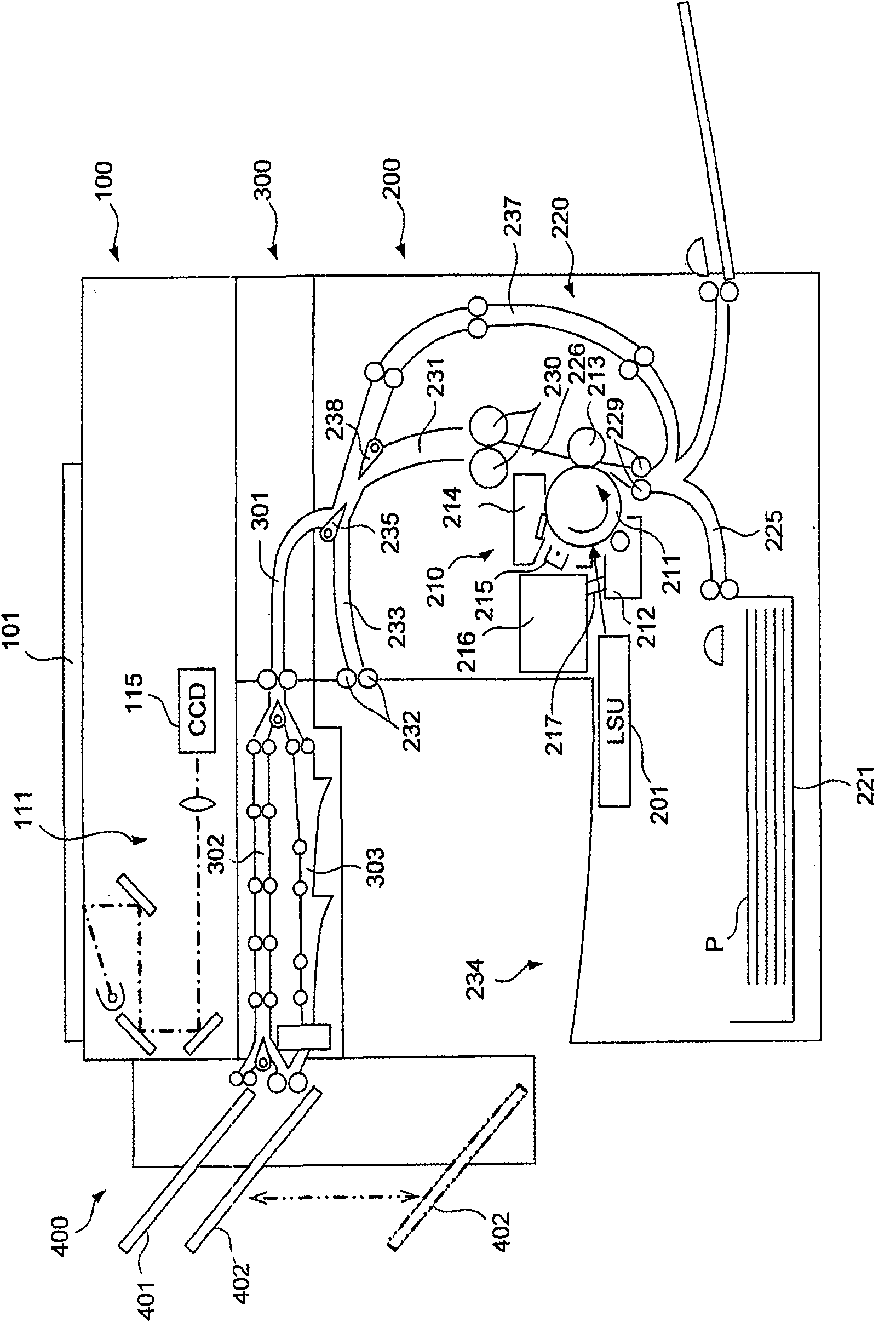
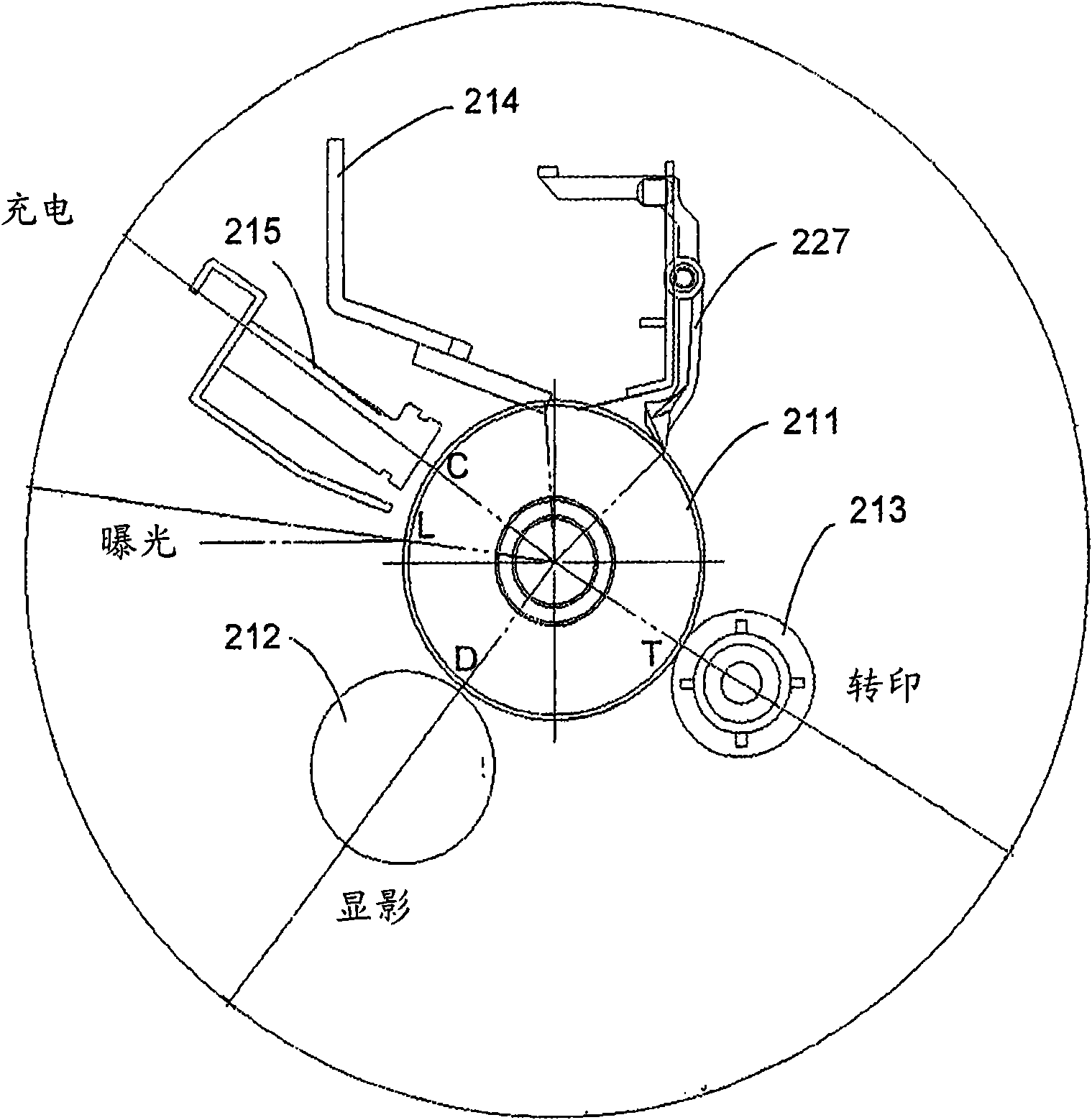
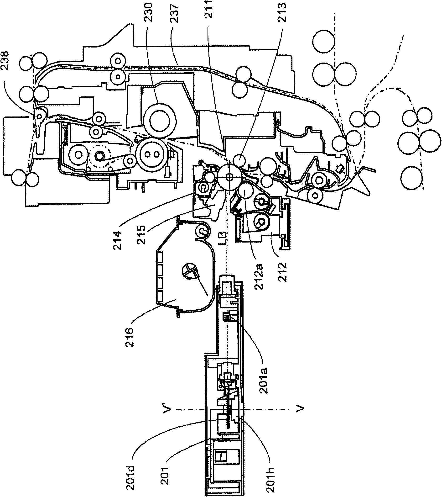
[0021] In the present invention, the light guide is cylindrical in shape. In electrophotographic processing the photoconductor is rotated about an axis while forming an image. Further, the material and physical properties of the photoconductor are not particularly limited as long as the material and physical properties are suitable for electrophotographic processing. When forming an image, the peripheral surface of the photoconductor moves in a single direction (in the second scanning direction). In the case of a drum-shaped photoconductor, the peripheral surface moves in response to the rotation of the drum.

[0022] The laser scanning section performs laser beam scanning on the outer peripheral surface in its moving direction and also in a direction perpendicular thereto (first scanning direction), and exposes the outer peripheral surface to the laser beam. The laser scanning section reflects and deflects a laser beam emitted from a fixed laser source on a side surface of ...


PUM


Abstract

The present invention relates to an image forming apparatus including: a cylindrical photoconductor; a laser scanning section that includes a polygonal mirror and allows a laser beam to reflect off the polygonal mirror and then irradiate a peripheral surface of the photoconductor, so that an electrostatic latent image is formed; an image development section for developing the electrostatic latentimage; and a toner storage section for storing the toner to be supplied to the image development section, wherein the image development section is disposed lower than a central axis of the photoconductor, the toner storage section is disposed above the image development section so as to form a space therebetween, and the laser scanning section is disposed so that the rotation axis of the polygonalmirror extends in a vertical direction, and the laser beam reflected from the polygonal mirror reaches to the photoconductor through the space and irradiates a portion of the peripheral surface, which is higher than the central axis of the photoconductor.

Description

technical field [0001] The present invention relates to an image forming apparatus, and more particularly to an arrangement of a photoconductor, an image developing section, a toner storage section, and a laser scanning section for electrophotographic processing in the image forming apparatus. Background technique [0002] In recent years, as image forming apparatuses are downsizing, the diameters of photoconductor drums used in electrophotographic processing are also being reduced. In the case of equipment with medium / low speed, a photoconductor drum having a diameter of about 30 mm is generally used. This trend stems from the need to reduce costs, conserve resources, and the like. In addition, the characteristics of photoconductor materials and the development of electrophotographic processing technology have enabled size reduction. Furthermore, due to reduction in size of the apparatus, a layout that allows feeding of a printing sheet in the vertical direction has been ...

Claims


Application Information

Patent Timeline
Patent Type & Authority Applications(China)
IPC IPC(8): G03G15/00G03G15/08G03G15/04
CPCG03G15/326G03G15/04036G03G15/0435
Inventor 若本宏治增田润也金子政人
Owner SHARP KK
Why Eureka
Try Eureka