Drainage devices and methods

a technology of suction device and draining device, which is applied in the direction of suction drainage container, intravenous device, other medical devices, etc., can solve the problems of not providing a mechanism by which an active drainage system can be efficiently converted to a passive one, and the suction characteristics remain poorly understood, so as to minimize the pain experienced by the patient, efficiently release, and reduce the effect of pain

Inactive Publication Date: 2007-02-01
RGT UNIV OF CALIFORNIA
View PDF36 Cites 45 Cited by
  • Summary
  • Abstract
  • Description
  • Claims
  • Application Information

AI Technical Summary

Benefits of technology

[0008] The present invention provides drainage devices and methods that are safe, effective, and useful for minimizing pain the pain experienced by the patient. Advantageously, the present invention provides techniques whereby negative pressure at or within a surgical drainage tube can be efficiently released when desired, so that the a drain can be removed from the patient without pulling local or entrapped tissues upon withdrawal, or without otherwise inducing tissue trauma or hemorrhage. These approaches are particularly in ensuring that a drainage device is truly off suction when unplugging a bulb drainage port prior to removal of the closed suction drain.

Problems solved by technology

Despite the wide use of these closed-system wound drain devices, their suction characteristics remain poorly understood.
What is more, many current approaches do not provide a mechanism whereby an active drainage system can be efficiently converted to a passive drainage system.

Method used


Image

  • Drainage devices and methods
  • Drainage devices and methods
  • Drainage devices and methods

Examples


Embodiment Construction

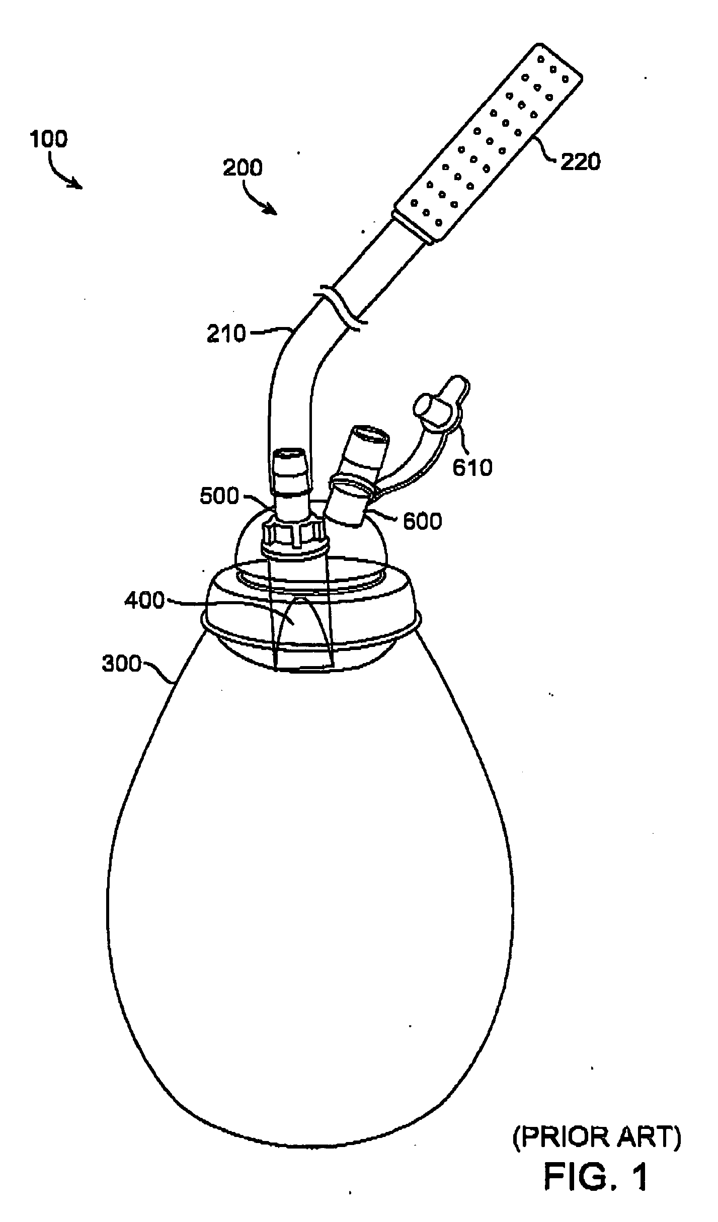
[0022] Turning now to the drawings, FIG. 1 illustrates a currently known drainage device 100 such as a closed system drainage suction device, which includes an input passage 200 having a drainage tube 210 and a drain 220. Drainage device 100 also includes a container 300, a one-way valve 400, a valve port 500, and a venting port 600 having a plug 610. As shown here, suction bulb reservoir or container 300 often has two ports 500 and 600. Venting port 600 is typically a tube-shaped lumen which connects the inside of container 300 to the outside. Venting port 600 can be plugged or unplugged with an attached plug 610. Valve port 500 can also be a tube-shaped lumen, across which lies one-way valve 400, which in many cases is a Heimlich valve. One-way valve 400 is oriented to allow one-way flow of fluid toward container 300. Surgical drainage tube 210, which can be a soft plastic tube exiting the patient's wound, connects drain 220 with valve port 500.

[0023] In many instances, drain 220...


PUM


Abstract

Active and passive wound drainage systems and method are provided. A drainage device includes an input passage for receiving the fluid from a site on or within the patient's body, a container for holding the fluid, and a reversible valve disposed between the input passage and the container. The reversible valve in an original configuration provides unidirectional fluid flow from the input passage toward the container, and in a reversed configuration provides fluid flow from the container toward the input passage.

Description

CROSS-REFERENCES TO RELATED APPLICATIONS [0001] NOT APPLICABLE STATEMENT AS TO RIGHTS TO INVENTIONS MADE UNDER FEDERALLY SPONSORED RESEARCH OR DEVELOPMENT [0002] NOT APPLICABLE REFERENCE TO A “SEQUENCE LISTING,” A TABLE, OR A COMPUTER PROGRAM LISTING APPENDIX SUBMITTED ON A COMPACT DISK [0003] NOT APPLICABLE BACKGROUND OF THE INVENTION [0004] This invention relates to the field of medical suction devices, and in particular to suction wound drains. [0005] Closed suction drains are ubiquitously used in medical practice to suction and collect fluid and other material from surgical wounds. For example, surgical wounds frequently benefit from drainage during the post operative period. This can involve removing fluid which is naturally expressed from the wounds, characterizing and measuring drained fluids, and monitoring the operative site for unexpected or undesired leakage of fluids. Hence, the drains are effective in promoting healing and recovery, while minimizing the likelihood of in...

Claims


Application Information

Patent Timeline
Patent Type & Authority Applications(United States)
IPC IPC(8): A61M1/00
CPCA61M1/0003A61M1/0005A61M1/0072A61M27/00A61M2205/075A61M1/0011A61M2209/06A61M1/63A61M1/82A61M1/682
Inventor GARCIA, MAURICE M.STOLLER, MARSHALL L.
Owner RGT UNIV OF CALIFORNIA
Why Eureka
Try Eureka