Hub unit for use in electrically movable wheels and vehicle comprising the hub unit

a technology of electrically movable wheels and hub units, which is applied in the direction of magnetic circuit rotating parts, magnetic circuit shapes/forms/construction, cycle equipment, etc., can solve the problems of heat generation, corresponding increase in cost, and stator b>3/b> is unable to effectively radiate heat, so as to prevent the winding 32 from overheating, reduce cost, and suppress the overheating of the winding 32

Inactive Publication Date: 2008-05-20
SANYO ELECTRIC CO LTD
View PDF29 Cites 58 Cited by
  • Summary
  • Abstract
  • Description
  • Claims
  • Application Information

AI Technical Summary

Benefits of technology

[0020]The motor housing 5 has no cylindrical wall 8 surrounding the outer peripheral surface of the metal plate stack 31 of the stator 3, so that even in the event of the windings of the stator 3 generating heat, the heat can be effectively released through the stator 3 to the outside of the motor housing 5, consequently preventing the windings 32 from overheating.
[0021]This obviates the need to suppress the overheating of the windings 32 by the conventional means, i.e., a cooling liquid enclosed within the hub 7.
[0022]Because the cylindrical wall 8 of the motor housing 5 can be dispensed with and further because there is no need for time and labor for enclosing the cooling liquid in the hub, the hub unit can be manufactured at a reduced cost. The hub unit can be obtained also with a weight reduction corresponding to the cylindrical wall 8 and the cooling liquid omitted.
[0023]The stator 3 can be given an increased outside diameter corresponding to the absence of the cylindrical wall 8, with the result that increased torque is available.

Problems solved by technology

The energization of the windings results in heat generation.
However, since the stator 3 is enclosed in the motor housing 5 which is closed, the stator 3 is unable to radiate heat effectively.
When the cooling liquid is enclosed in the hub 7, means or measure is needed for preventing leakage of the liquid to result in a corresponding increase in cost.

Method used


Image

  • Hub unit for use in electrically movable wheels and vehicle comprising the hub unit
  • Hub unit for use in electrically movable wheels and vehicle comprising the hub unit
  • Hub unit for use in electrically movable wheels and vehicle comprising the hub unit

Examples


second embodiment

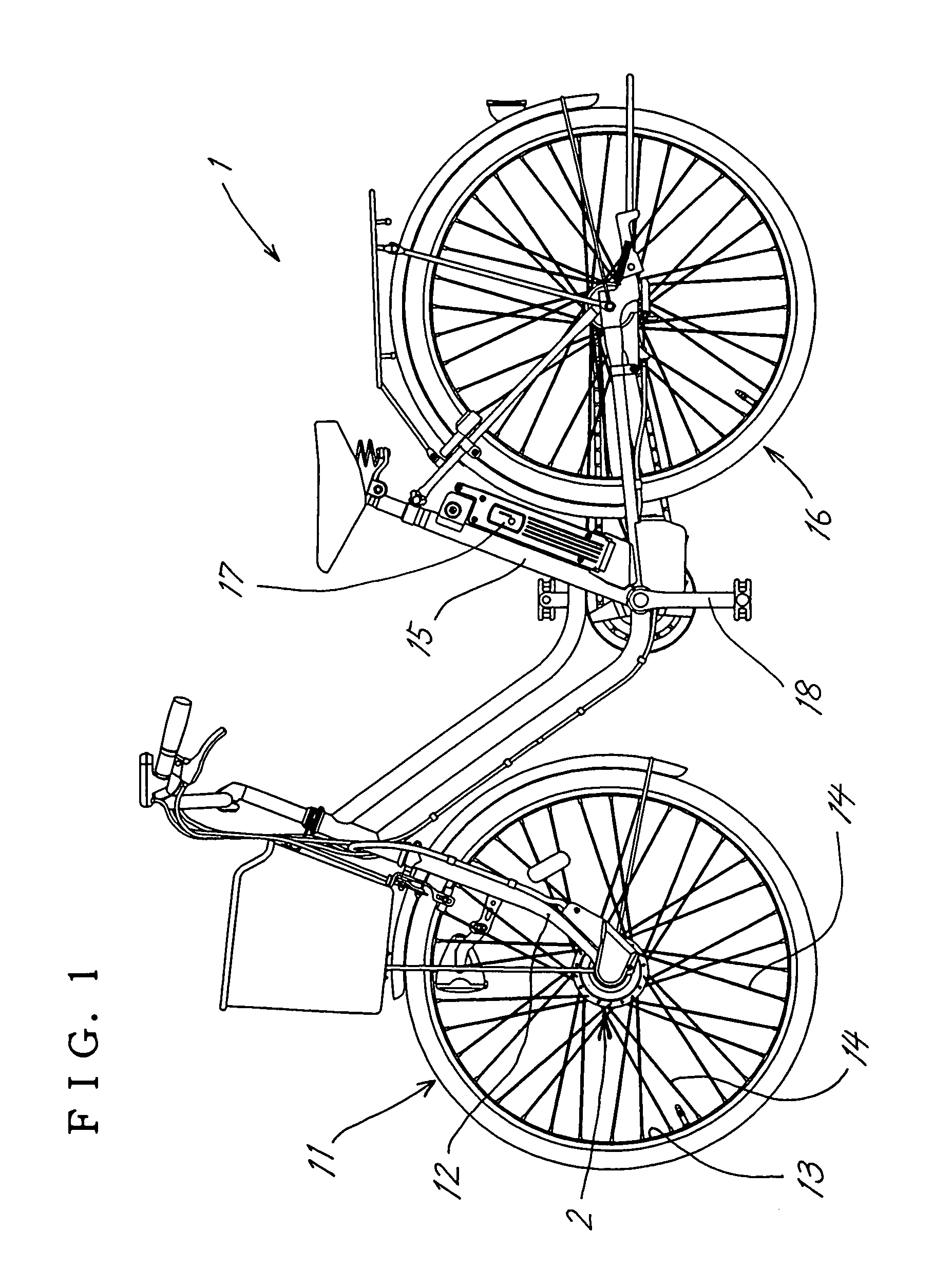
[0081]FIG. 6 shows hub unit 2, and FIG. 7 is a perspective view of the same with a hub main body removed.

[0082]This embodiment has the same construction as the hub unit 2 shown in FIG. 2 except the motor housing 5 and the means for attaching the metal plate stack 31 of the stator 3 to the motor housing. Accordingly, the same description will not be given repeatedly.

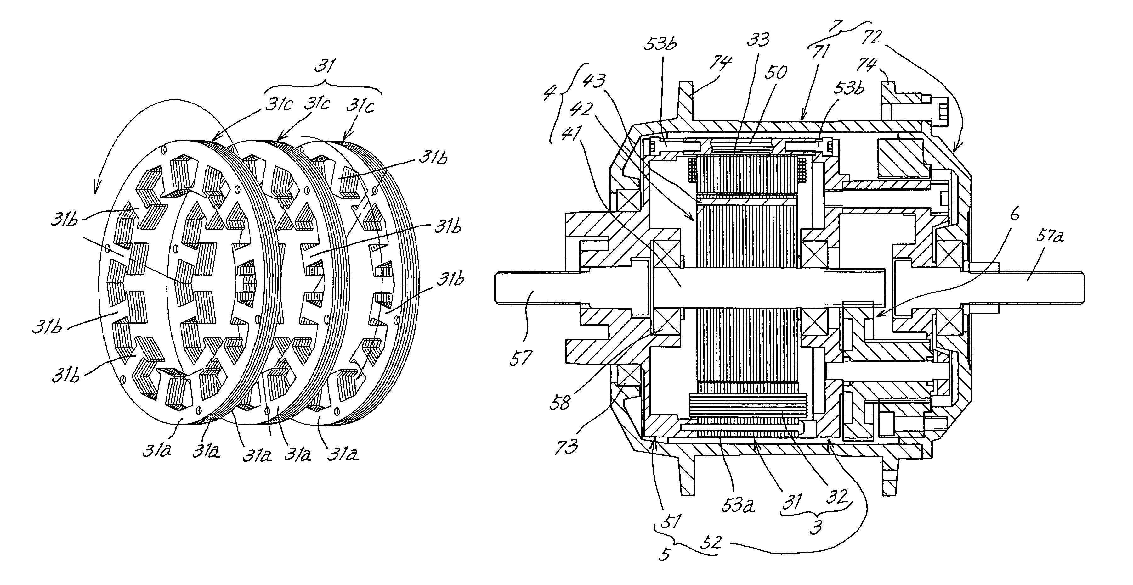
[0083]The motor housing 5 comprises a first end plate 51, second end plate 52, a plurality of spacer rods 50 interposed between the two end plates 51, 52 for determining the distance therebetween, and fastening bolts 53b, 53b inserted through the end plate 51 or 52 and screwed into the spacer rods 50.

[0084]The spacer rods 50 have a length slightly larger than the thickness of the metal plate stack 31 of the stator 3.

[0085]The metal plate stack 31 is provided in its outer peripheral portion with grooves 33 for the respective spacer rods to fit in.

[0086]The stack 31 is fastened to the first end plate 51 or the second end pl...

third embodiment

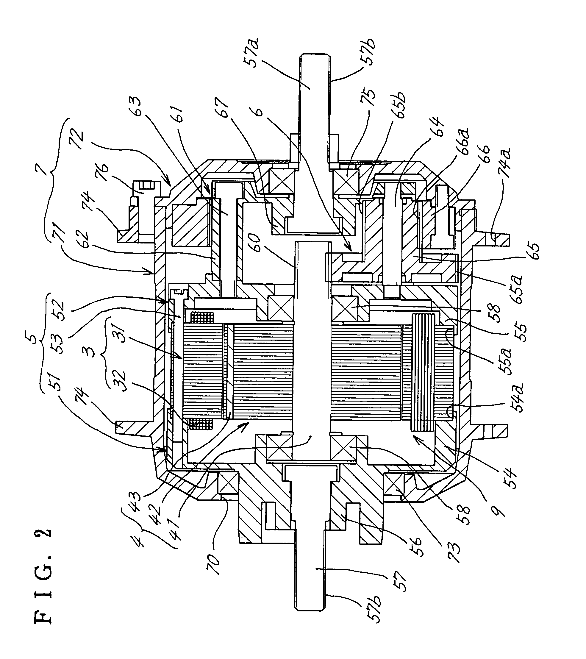
[0089]FIG. 8 shows hub unit 2. This embodiment has the same construction as the hub unit 2 shown in FIG. 2 except that a single fixing support shaft 57 extends through a hub 7 and that a rotor 4 is provided on a tubular shaft 44 rotatably fitting around the support shaft 57.

[0090]When the fixing support rods 57, 57a extend through respective opposite ends of the hub 7 to project outward therefrom and are each independent of the rotating shaft 41 of the rotor 4 as in the hub unit 2 shown in FIG. 2, the hub unit has a complex construction. Furthermore, errors involved in machining or assembling the components are likely to cause the deflection of the axes of the support shafts 57, 57a at the opposite ends, whereas the third embodiment can be free of these problems.

[0091]The hub unit 2 of the present invention, which is useful for electrically assisted bicycles, can be embodied alternatively for hubs for vehicles having wheels, for example, for wheelchairs.

[0092]The individual fixing s...


PUM


Abstract

A hub unit for use in electrically assisted bicycles has an improved effect to radiate heat from a stator. A hub (7) has inner teeth (66a) meshable with planetary gears (65) and a fixing support shaft (57) projecting from opposite ends of the hub and provided fixedly relative to a motor housing (5). The motor housing (5) has no cylindrical wall (8) covering the outer peripheral surface of the stator (3) but leaves the stator outer peripheral surface exposed to effectively release the heat generated by the windings of the stator.

Description

FIELD OF THE INVENTION[0001]The present invention relates to hub units for use in electrically movable wheels, and to electrically assisted bicycles, wheelchairs and like vehicles comprising the hub unit.BACKGROUND OF THE INVENTION[0002]FIG. 9 shows an electrically movable wheel hub unit 2 for an electrically assisted bicycle.[0003]The electrically movable wheel hub unit (hereinafter referred to as the “hub unit”) has a motor 9 comprising a stator 3 and a rotor 4, a hub 7 enclosing the motor 9 therein and rotatingly drivable at a reduced speed by the motor 9 and a planetary gear reduction mechanism 6, and fixing support shafts 57, 57a disposed on the axis of rotation of the hub 7 fixedly relative to a motor housing 5 and projecting outward from the hub 7.[0004]The stator 3 comprises a stack 31 of metal plates and windings 32 provided on the metal plate stack 3.[0005]The motor housing 5 comprises a cylindrical wall 8 and a pair of end plates 51, 52 closing opposite end openings of th...

Claims


Application Information

Patent Timeline
Patent Type & Authority Patents(United States)
IPC IPC(8): H02K1/18H02K1/22H02K1/28H02K7/00B60B27/00B62J6/12B62M6/65H02K5/00H02K5/04H02K5/15H02K7/116H02K7/18H02K9/00H02K9/14
CPCB62J6/12H02K5/04H02K7/116H02K7/1846B60L3/0061B60L11/007B60L11/1805B60L11/1877B62M6/65Y02T10/641H02K9/00H02K9/14B60L2200/12B60L2240/36Y02T10/7005Y02T10/705B60L50/20B60L50/52B60L50/66Y02T10/64Y02T10/70
Inventor TANAKA, TATSUAKITOMOSHIGE, KAZUHIROADACHI, RYOHEI
Owner SANYO ELECTRIC CO LTD
Why Eureka
Try Eureka