Ferrite core and transformer using the same
A transformer and cavity technology, applied in the field of transformers, to achieve the effects of compact equipment, increased wire diameter, and reduced costs
- Summary
- Abstract
- Description
- Claims
- Application Information
AI Technical Summary
Problems solved by technology
Method used
Image
Examples
no. 1 approach
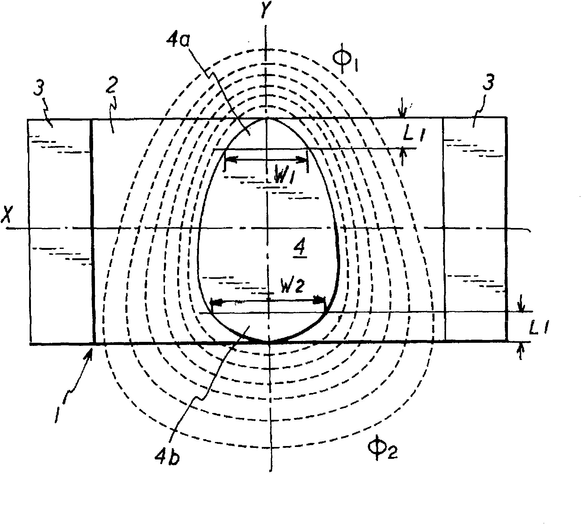
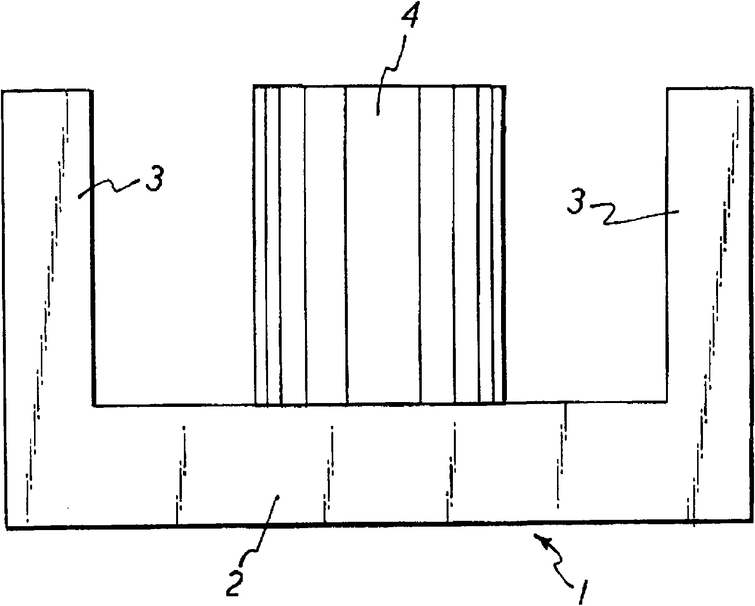
[0086] figure 1 is a plan view illustrating an embodiment of a ferrite core according to the present invention, and figure 2 is the front view of the ferrite core. The ferrite core 1 has an end surface 2 , a pair of outer columns 3 protruding from the end surfaces 2 , and a center column 4 protruding from the end surface 2 between the pair of outer columns 3 . The direction where the ends of the outer column 3 and the middle column 4 are aligned is defined as the X-axis direction, and the direction perpendicular to the X-axis is defined as the Y-axis direction. In both end portions in the Y-axis direction, the width W1 ( figure 1 The width at a predetermined distance L1 from the end on the upper side) is smaller than the width W2 at the same distance L1 from the other end 4b (W1<W2). In the present embodiment according to the invention, the central column 4 has an oval cross-section. The outer column 3 has a constant width in the Y-axis direction.
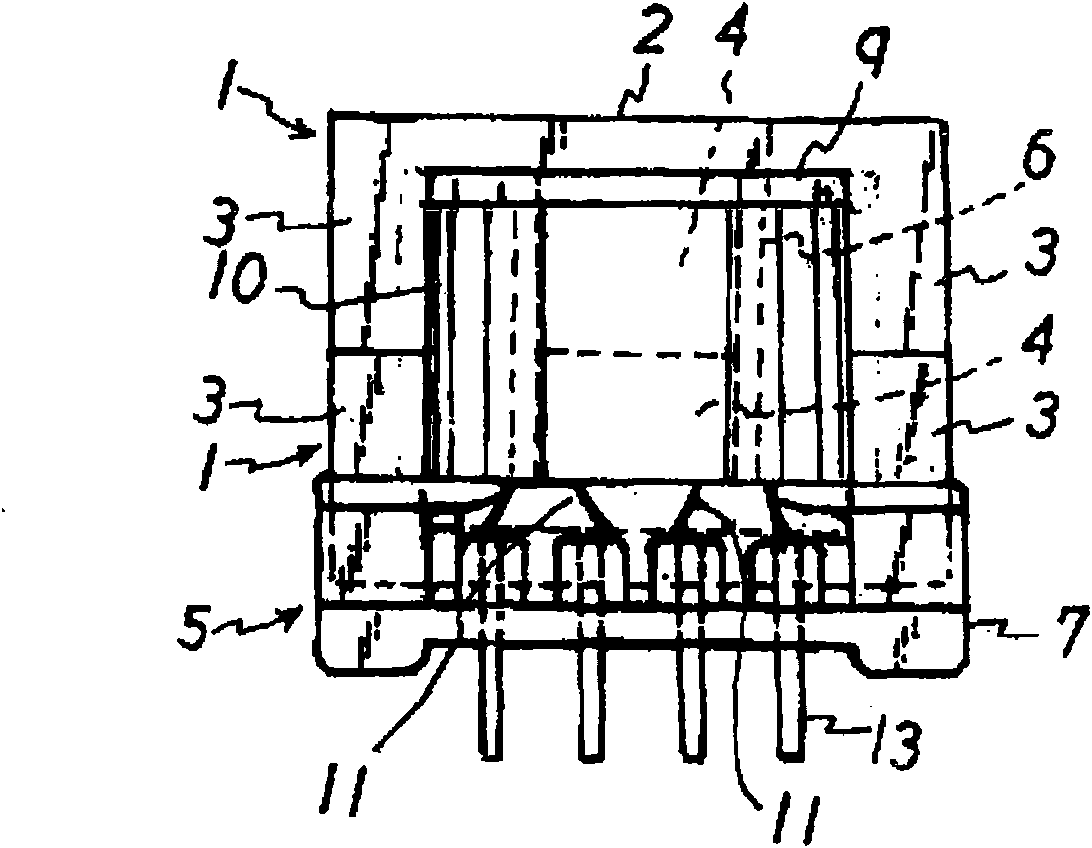
[0087] image 3 is...
no. 2 approach
[0097] Figure 9 is a plan view illustrating an embodiment of a ferrite core according to the present invention, and Figure 10 This is the side view of the ferrite core. The ferrite core 101 has an end surface 102 , a pair of outer columns 103 protruding from the end surface 102 , and a center column 104 protruding from the end surface 102 between the pair of outer columns 103 . The direction in which the positions of the respective ends of the outer column 103 and the center column 104 are aligned is defined as the X-axis direction, and the direction perpendicular to the X-axis is defined as the Y-axis direction. Assuming that the origin O is the center of the Y-axis direction, measurements are made at two positions at equal distances +Δy and −Δy from the origin in two directions, respectively, and the center column 104 has different widths W1 and W2 in the X-axis direction ( W1
no. 3 approach
[0111] Figure 24 to Figure 26 are respectively the front view, side view and rear view of the third embodiment of the bobbin according to the present invention, and Figure 27 is along Figure 26 Sectional view of line E-E in . These embodiments illustrate a vertical transformer in which terminal boards 207 and 208 are provided on only one side of the boards 203 and 204 on the board 203 , and the primary side terminal 205 and the secondary side terminal 206 are mounted on the terminal board. The protective plates 203 and 204 are formed on two ends of the drum 202 , and the drum 202 is used for winding the coil on the coil frame 201 .
[0112] exist Figure 27 Among them, O represents the vertical and horizontal center points of the reel 202 . Here, in the cross section perpendicular to the cavity winding core of the reel 202, the center line of the facing direction of the terminal boards 207 and 208 is the Y axis, and in this cross section, it is perpendicular to the facing...
PUM
 Abstract
Description
Claims
Application Information
 - R&D
- Intellectual Property
- Life Sciences
- Materials
- Tech Scout
- Unparalleled Data Quality
- Higher Quality Content
- 60% Fewer Hallucinations
Browse by: Latest US Patents, China's latest patents, Technical Efficacy Thesaurus, Application Domain, Technology Topic, Popular Technical Reports.
© 2025 PatSnap. All rights reserved.Legal|Privacy policy|Modern Slavery Act Transparency Statement|Sitemap|About US| Contact US: help@patsnap.com


