
Hydraulic power management system

A technology of power management and pressure, applied in fluid pressure actuators, engine control, machine/engine, etc., can solve problems such as internal combustion engine stalling

Inactive Publication Date: 2012-06-20
CLARK EQUIP CO INC
View PDF4 Cites 0 Cited by
  • Summary
  • Abstract
  • Description
  • Claims
  • Application Information

AI Technical Summary

Problems solved by technology

However, such a system may also allow the pressure of the fluid supplied to the auxiliary device to reach a level that would stall the internal combustion engine, for example, when the operator requires the auxiliary tool to work at its maximum capacity

Method used


Image

  • Hydraulic power management system
  • Hydraulic power management system
  • Hydraulic power management system

Examples


Embodiment Construction

[0013] Before describing any embodiments of the present invention in detail, it should be understood that the present invention is not limited to the application of the detailed structure and component configuration presented below or shown in the drawings. The present invention may be other embodiments, and may be implemented or carried out in various ways. Moreover, it should be understood that the wording and terminology used herein are for description and should not be considered as limiting. Here, "including", "including" or "having" and its variations mean to include the items listed later and their equivalents and additional items. Unless there is an explanation or limitation to the contrary, the terms "installation", "connection", "support" and "connection" and their deformations are widely adopted, and include direct or indirect installation, connection, support and connection. Moreover, "connected" and "coupled" are not limited to physical or mechanical connections o...


PUM


Abstract

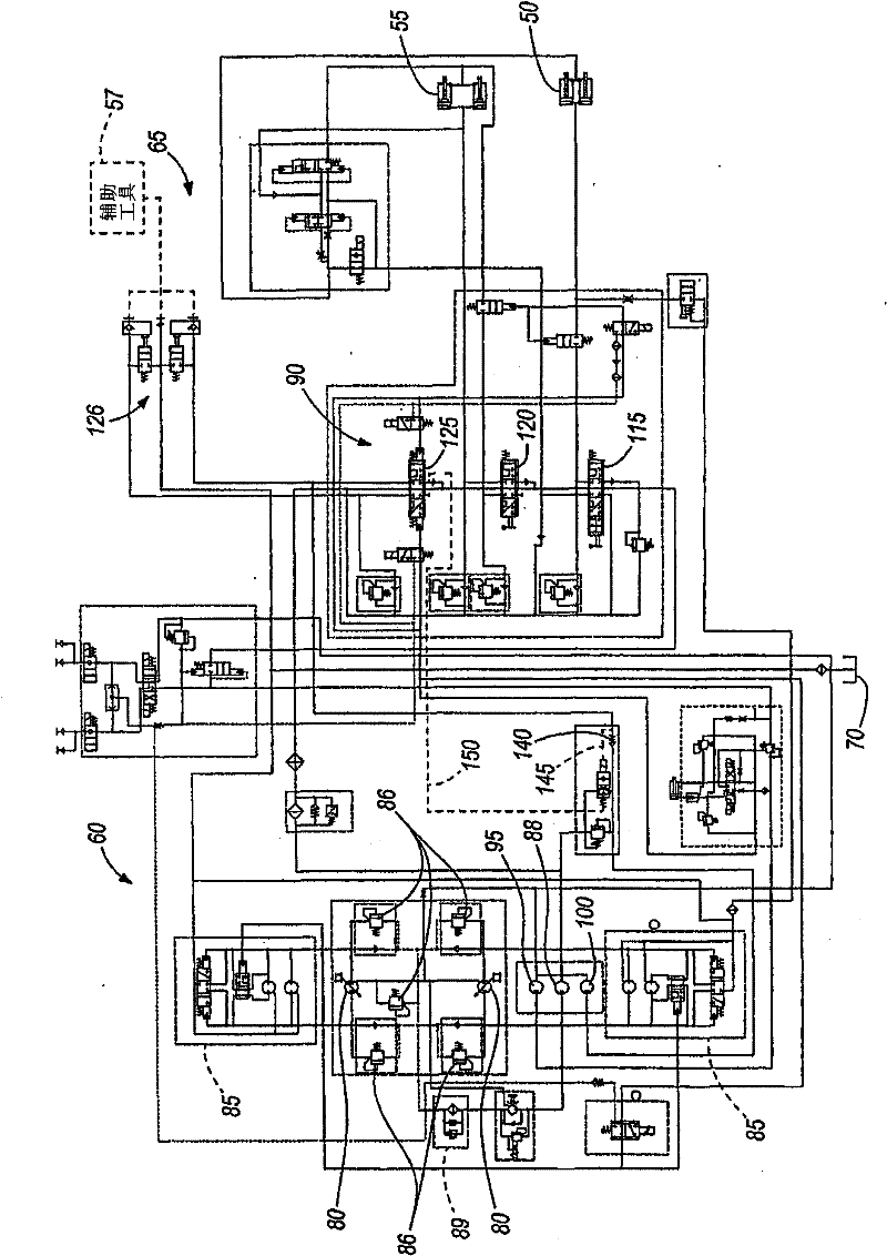
A machine (10) having a hydraulic power management system (105). The machine includes an internal combustion engine (30) driving first and second fixed displacement pumps (95, 100) to produce a combined flow of pressurized fluid. Main (50, 55, 45) and auxiliary (57) implements are operable in response to a flow of pressurized fluid, and a control valve (90) selectively directs the combined flow to the main and auxiliary implements. A power management system (105) is operable to stop the flow of pressurized fluid to the main implement (50, 55, 45) from the second pump (100) when the pressure of the combined flow exceeds a pressure indicative of the impending engine stall. A means for providing the combined flow to the auxiliary implement without regard to the pressure of the combined flow is also provided, and may take the form of a power management override (150) or bypass mechanism (110).

Description

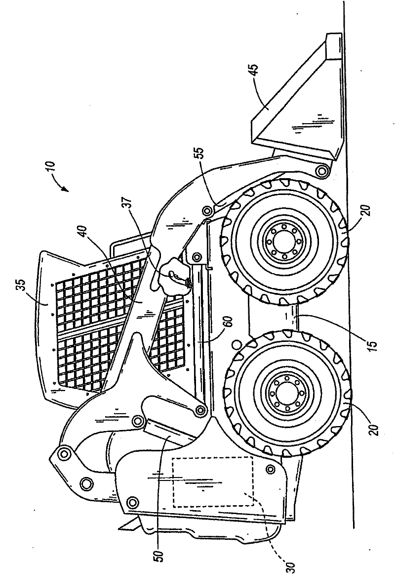
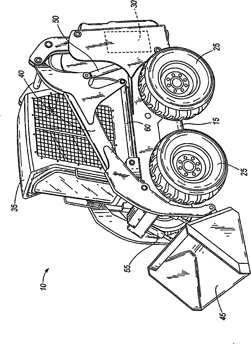
Technical field [0001] The present invention relates to a hydraulic power management system, which can be used, for example, in a compact structure vehicle, such as a skid steer loader. Background technique [0002] Skid steer loaders are usually equipped with a driving and steering system and main equipment, such as a lifting arm with a bucket attachment. With the hydraulic pump driven by the internal combustion engine, the hydraulic fluid is supplied to the drive system under pressure and supplied to the main equipment. [0003] In many skid steer loaders, the lifting arm rises and falls under the action of the lifting cylinder, and the bucket is rolled and dumped under the action of the swing cylinder. The bucket can be replaced, or various auxiliary tools, such as augers or rock hammers that provide additional functions for the skid steer loader, can be used to enhance performance. The main valve usually responds to a joystick or other control device to control the supply of ...

Claims


Application Information

Patent Timeline
Patent Type & Authority Patents(China)
IPC IPC(8): E02F9/22F02D29/00F15B11/16
CPCE02F9/226F15B2211/7053F15B11/17F15B2211/20576E02F9/2292F15B2211/3116F15B2211/20523E02F9/2246F15B2211/20538F02D29/04E02F9/2239F15B2211/50536
Inventor 斯科特·N·舒约瑟夫·A·圣·奥宾
Owner CLARK EQUIP CO INC
Learn More