Wavelength converter
一种波长转换器、波长的技术,应用在仪器、非线性光学、光学等方向,能够解决未检验重复地改变张力的方法、未披露施加张力的具体方法等问题
- Summary
- Abstract
- Description
- Claims
- Application Information
AI Technical Summary
Problems solved by technology
Method used
Image

Examples
no. 1 example
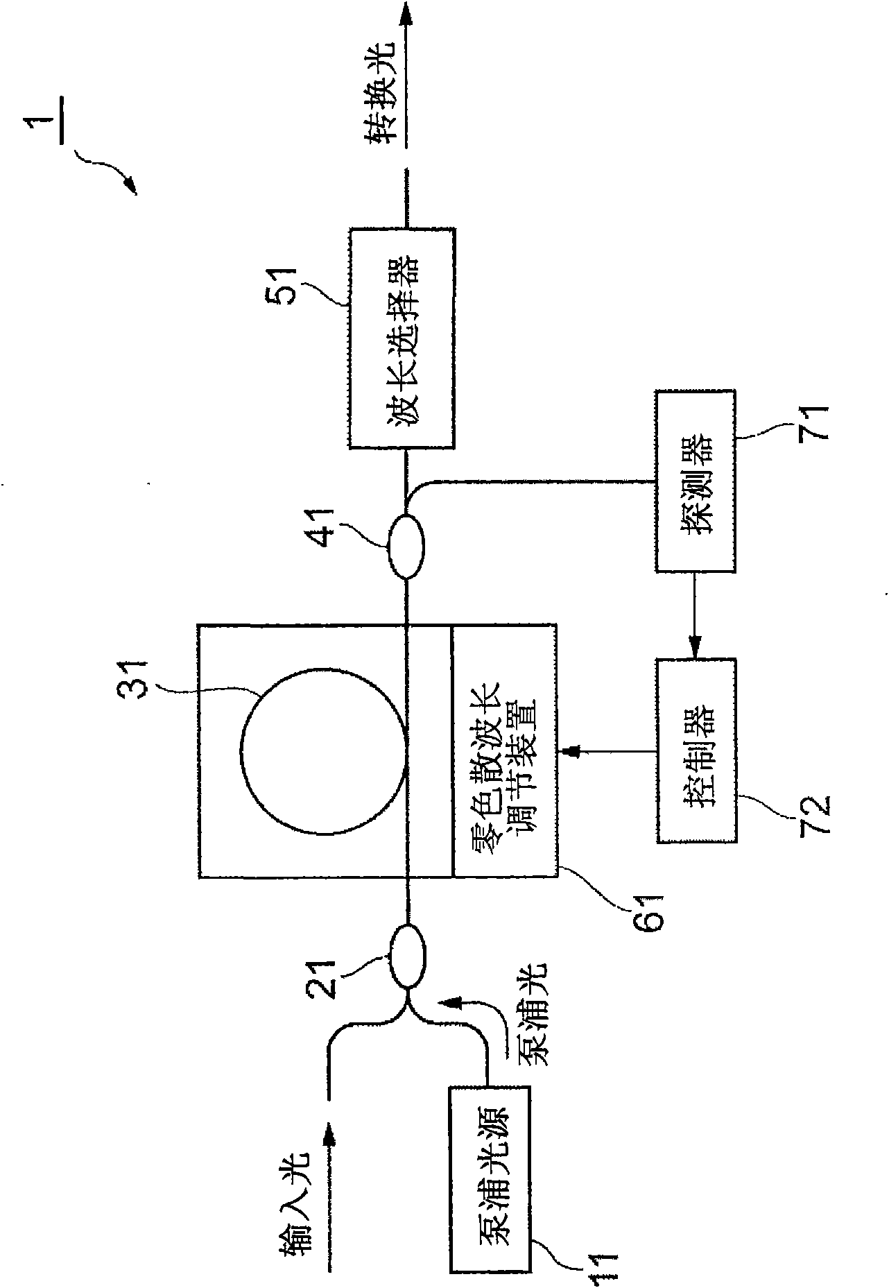
[0028] figure 1 is a conceptual diagram of the wavelength converter 1 according to the first embodiment of the present invention. In the wavelength converter 1, the pumping light source 11 outputs pumping light. The optical multiplexer 21 receives the input light to be converted and the pumping light output from the pumping light source 11, and the optical multiplexer 21 mixes and outputs the input light and the pumping light. The optical fiber 31 receives at one end thereof the input light and the pumping light that have been mixed and output from the optical multiplexer 21, and guides the input light and the pumping light. The optical fiber 31 generates converted light using a nonlinear optical phenomenon (four-wave mixing) generated when the optical fiber 31 guides input light and pump light, and outputs the converted light from the other end thereof. The optical fiber 31 has a zero-dispersion wavelength near the wavelength of the pump light. The light output from the ab...
no. 2 example
[0047] Figure 8 is a conceptual diagram of a wavelength converter 2 according to a second embodiment of the present invention. The respective optical fibers 31A and 31B are similar to the optical fiber 31 of the first embodiment. Optical fibers 31A and 31B may be of the same type or of different types. Each of the zero-dispersion wavelength adjustment devices 61A and 61B is similar to the zero-dispersion wavelength adjustment device 61 of the first embodiment. The zero-dispersion wavelength adjusting device 61A adjusts the zero-dispersion wavelength of the optical fiber 31A. The zero dispersion wavelength adjusting device 61B adjusts the zero dispersion wavelength of the optical fiber 31B.
[0048] The operation of the wavelength converter 2 is as follows. The input light to be converted and the pump light output from the pump light source 11 are mixed via the optical multiplexer 21 and input to one end of the optical fiber 31A. A nonlinear optical phenomenon occurs when...
no. 3 example
[0051] Figure 9 is a conceptual diagram of a wavelength converter 3 according to a third embodiment of the present invention. In addition to the structure of the wavelength converter 2 , the wavelength converter 3 also includes an optical demultiplexer 12 and an optical multiplexer 22 . Optical demultiplexer 12 branches the pump light output from pump light source 11 , and outputs the branched pump light to optical multiplexers 21 and 22 . The input light to be converted and the pump light output from and arriving at the optical demultiplexer 12 are input into the optical multiplexer 21 . The optical multiplexer 21 mixes input light and pump light and outputs it into the optical fiber 31A. The light that has been output from the optical fiber 31A and the pump light output from and arriving at the optical demultiplexer 12 are input into the optical multiplexer 22 . The optical multiplexer 22 mixes and outputs these lights into the optical fiber 31B.
[0052] The operation ...
PUM
| Property | Measurement | Unit |
|---|---|---|
| wavelength | aaaaa | aaaaa |
| color dispersion value | aaaaa | aaaaa |
Abstract
Description
Claims
Application Information
 - Generate Ideas
- Intellectual Property
- Life Sciences
- Materials
- Tech Scout
- Unparalleled Data Quality
- Higher Quality Content
- 60% Fewer Hallucinations
Browse by: Latest US Patents, China's latest patents, Technical Efficacy Thesaurus, Application Domain, Technology Topic, Popular Technical Reports.
© 2025 PatSnap. All rights reserved.Legal|Privacy policy|Modern Slavery Act Transparency Statement|Sitemap|About US| Contact US: help@patsnap.com