
Ventilation system for clean rooms

A technology for ventilation systems and clean rooms, applied in the field of ventilation systems, can solve problems such as large power consumption, and achieve the effects of saving power, reducing air intake, and being convenient to use

Inactive Publication Date: 2010-02-10
WUJIANG HONGDA VENTILATION REFRIGERATION EQUIP FACTORY
View PDF0 Cites 5 Cited by
  • Summary
  • Abstract
  • Description
  • Claims
  • Application Information

AI Technical Summary

Problems solved by technology

[0005] Due to the high cleanliness, the clean room generally adopts a relatively positive pressure form. The air intake and return air of the entire clean area require a large fan delivery capacity to maintain cleanliness, and the power consumption is quite large.

Method used


Image

  • Ventilation system for clean rooms

Examples


Embodiment Construction

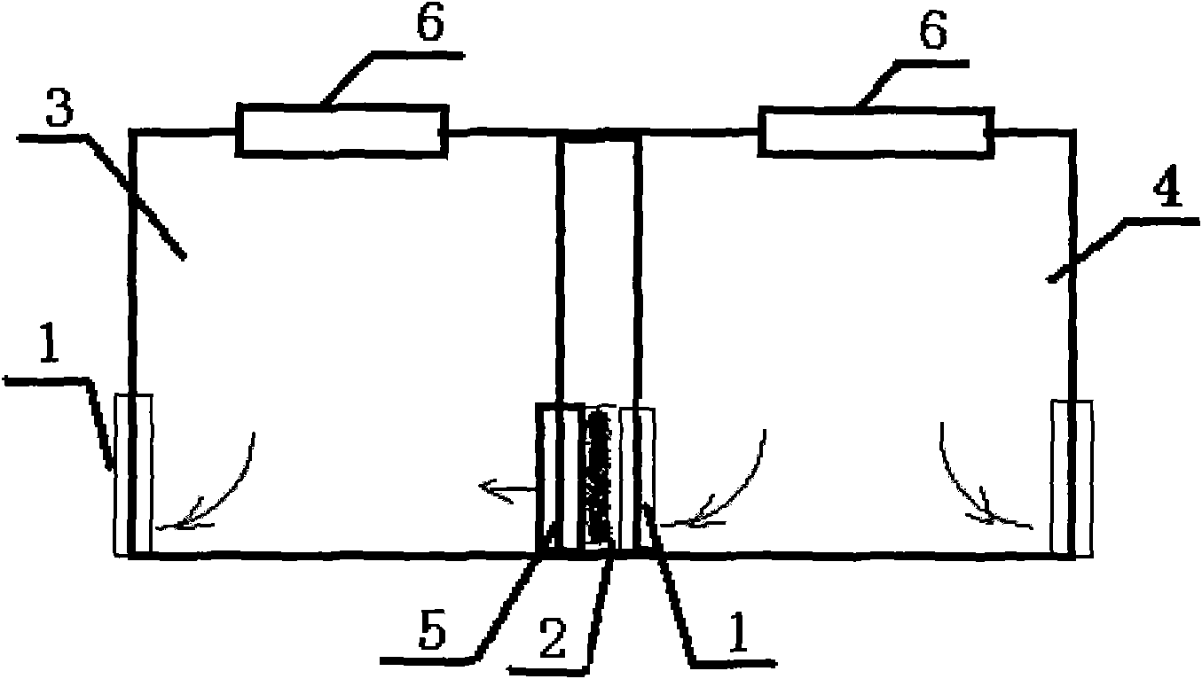
[0011] The present invention will be further described below in conjunction with the accompanying drawings: the lower clean room 3 of the clean level is provided with a supplementary air outlet 5, and the supplementary air outlet 5 is connected with the air inlet unit 6 of the clean room, and the cleanliness level adjacent to it is higher The air outlet unit 1 of the clean room 4 is connected, and a filter 2 is arranged in the middle. The aperture of the filter 2 is different between different clean levels, and the air intake unit 6 of the clean room 3 with a lower clean level is adjusted according to the amount of supplementary air. The air intake volume does not affect the air volume of the air outlet unit 1. By analogy, the air outlet from the clean room with the highest cleanliness level is used as the initial supplementary air source until the air outlet unit 1 with the lowest cleanliness level completes the air outlet.

[0012] Applying the present invention to a clean ro...


PUM


Abstract

The invention provides a ventilation system for clean rooms, which comprises wind inlet units, wind outlet units and a control unit, wherein a wind replenishing opening is arranged below a clean roomwith a lower clean level; the wind replenishing opening is connected with the wind inlet unit of the clean room with a lower clean level and is connected with the wind outlet unit of an adjacent cleanroom with a higher clean level; and filter screens are arranged in the middle of the ventilation system, and the apertures of the filter screens based on different clean levels are different. The wind inlet unit of the clean room with a lower clean level regulates the wind inlet quantity according to the wind replenishing quantity without influencing the wind outlet quantity of the wind outlet unit, and by analogy, the wind exhaustion of a clean room with a highest clean level is used as a primary wind replenishing source, the wind exhaustion is thoroughly finished until a wind outlet unit with a lowest clean level is replenished. The invention has the effects that the wind replenishing opening is arranged below the clean room, thus large-area turbulent flow of the upward air can not occur, the wind outlet quantity is reduced simultaneously, and a larger amount of electric quantity is saved.

Description

technical field [0001] The invention relates to a ventilation system, in particular to a clean room ventilation system. Background technique [0002] Clean room (Clean Room), also known as clean room or clean room. It is the basis of pollution control. Mass production of contamination-sensitive parts is impossible without a clean room. In FED-STD-2, a clean room is defined as a room with air filtration, distribution, optimization, construction materials and devices, in which specific regular operating procedures are used to control the concentration of airborne particulates to achieve an appropriate particulate cleanliness level . [0003] Clean room refers to the removal of particulates, harmful air, bacteria and other pollutants in the air within a certain space, and the control of indoor temperature, cleanliness, indoor pressure, air velocity and air distribution, noise vibration, lighting, and static electricity. A room with a special design within a certain range of...

Claims


Application Information

Patent Timeline
Patent Type & Authority Applications(China)
IPC IPC(8): F24F3/16F24F13/28
Inventor 周志刚
Owner WUJIANG HONGDA VENTILATION REFRIGERATION EQUIP FACTORY
Learn More