Method and apparatus for spinning staple fibres on ring-spinning machines

A technology of ring spinning machine and short fiber, which is applied in the field of short fiber spinning, which can solve the problems of increasing yarn ball resistance, power increase, increasing energy demand, etc., and achieves the effect of energy saving and energy saving

Inactive Publication Date: 2010-02-10
DITF DEUT INST FUR TEXTIL UND FASERFORSCHUNG DENKENDORF
View PDF3 Cites 5 Cited by
  • Summary
  • Abstract
  • Description
  • Claims
  • Application Information

AI Technical Summary

Problems solved by technology

Even though the diameter of the balls is reduced to a great extent and therefore the ball confinement ring can be eliminated, this design increases the spindle speed and increases the energy demand
In addition, the joint set at the head of the spindle to drive the twisting part makes the yarn ball larger, thereby increasing the resistance of the yarn ball, resulting in an increase in power

Method used


Image

  • Method and apparatus for spinning staple fibres on ring-spinning machines
  • Method and apparatus for spinning staple fibres on ring-spinning machines
  • Method and apparatus for spinning staple fibres on ring-spinning machines

Examples


Embodiment Construction

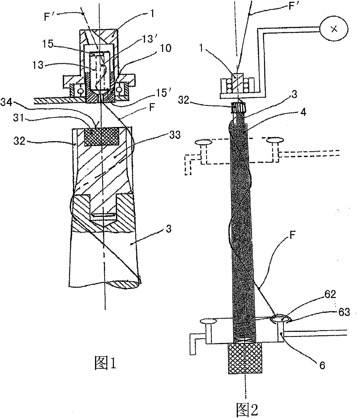
[0022] The yarn guiding device consists of a yarn guiding device 1 arranged above the spindle, which has a twisting part 10, which contains a braking mechanism. The braking mechanism consists of a tappet 13 which has a core 13' extending coaxially with the axis of rotation around which the upper unfinished yarn F coming out from the spindle 3 to the outlet of the draw frame surrounds. On the core member 13', there are an upper edge 15 and a lower edge 15' on which the yarn F passed through the yarn-guiding device 1 rests and is brought into rotation when the twisting member 10 turns.

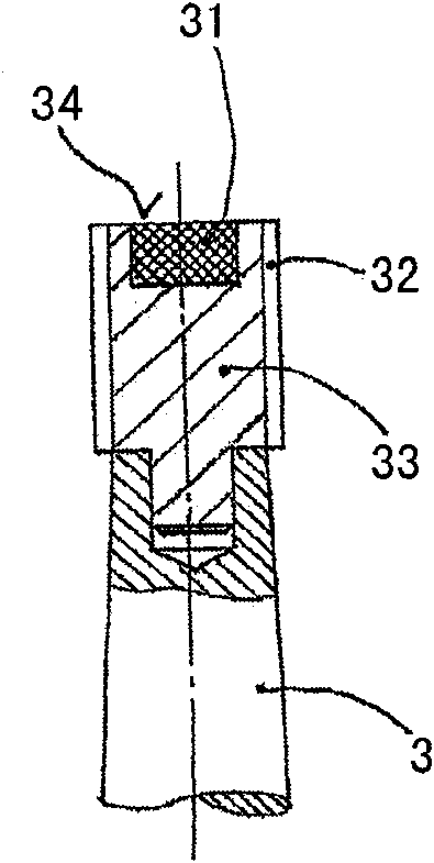
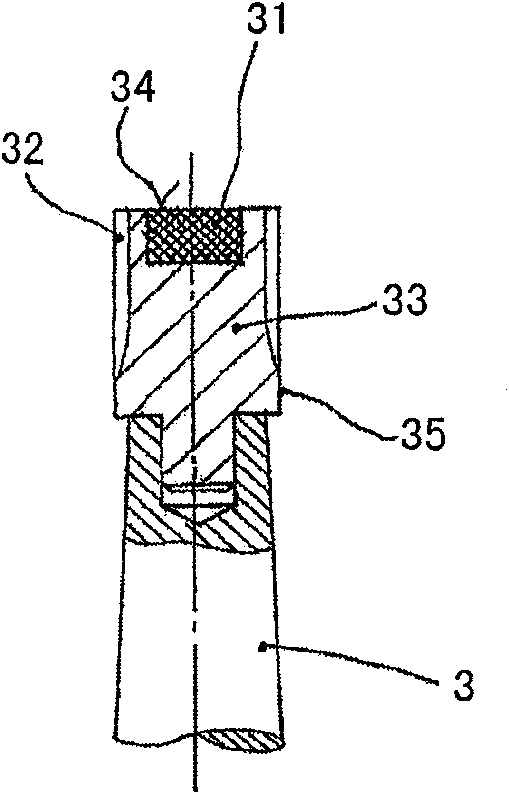
[0023] The part facing the spindle 3 on the twisting member 10 is used as a magnet, and forms a coupling magnet with the accessory 33 on the spindle 3 that is also equipped with a permanent magnet 31, so that the twisting member 10 rotates at the same speed as the spindle 3. The distance between the spindle fitting 33 and the twisting element 10 is determined by the necessary magnetic field to e...


PUM


Abstract

The invention relates to a method for spinning staple fibres on ring-spinning machines, wherein a staple fibre composite is drawn in a drawing frame and, during exit from the drawing frame, is twistedto form a thread and is wound up by means of a traveler device. The fibre composite (F') which emerges from the drawing frame runs through a thread guide device (1) which has a twisting apparatus (10) which is equipped with a brake device (13, 13'). The completely twisted thread (F) is guided over a spindle attachment (33) which is provided with grooves (32, 35), immediately after leaving the twisting apparatus (10). The method is carried out by way of an apparatus for spinning staple fibres on ring-spinning machines, which apparatus comprises a thread guide device which has a twisting element which is arranged at a spacing above the upper end of the ring spindle and is coupled to the ring spindle via a magnetic force field. An attachment (33) which is arranged on the ring spindle (3) andhas grooves (32, 35) on its circumference for driving the thread (F) which emerges from the twisting element (10) is connected behind the twisting element (10).

Description

technical field [0001] The invention relates to a method of staple fiber spinning, in particular staple fiber spinning, on a ring spinning frame, characterized in that the staple fiber components are drawn into a draw frame and then twisted to form a yarn. When it comes out of the draw frame, it is wound up with the aid of traveler equipment. The fiber components coming out of the draw frame then pass through a yarn-guiding device with a twisting device equipped with brakes driven synchronously with the spindles to twist the fiber mixture. At the same time, the invention also provides a device for implementing the method. Background technique [0002] As we all know, in most cases, the yarn on the ring spinning machine mainly breaks in the so-called spinning zone between the draw frame and the yarn guide device, where the slub coming out of the draw frame has not yet Strong enough to withstand every yarn tension peak. Furthermore, conventional yarn guide devices, so-calle...

Claims


Application Information

Patent Timeline
Patent Type & Authority Applications(China)
IPC IPC(8): D01H1/02D01H7/18D01H7/92
CPCD01H1/02D01H7/92D01H7/18
Inventor 彼得·阿茨特于尔根·施奈德乌韦·海特曼
Owner DITF DEUT INST FUR TEXTIL UND FASERFORSCHUNG DENKENDORF
Why Eureka
Try Eureka