
Vibration control equipment

An anti-vibration device and anti-vibration technology, applied in non-rotational vibration suppression, mechanical equipment, low internal friction springs, etc., can solve problems such as increased production costs and cumbersome assembly operations, and achieve the effects of easy assembly and reduced production costs.

Inactive Publication Date: 2010-02-10
BRIDGESTONE CORP
View PDF2 Cites 11 Cited by
  • Summary
  • Abstract
  • Description
  • Claims
  • Application Information

AI Technical Summary

Problems solved by technology

Therefore, there is a problem that the assembly work is cumbersome
In addition, since the above-mentioned press-fitting process requires a press-fitting tool, etc., there is a problem that the production cost increases.

Method used


Image

  • Vibration control equipment
  • Vibration control equipment
  • Vibration control equipment

Examples


no. 1 Embodiment approach

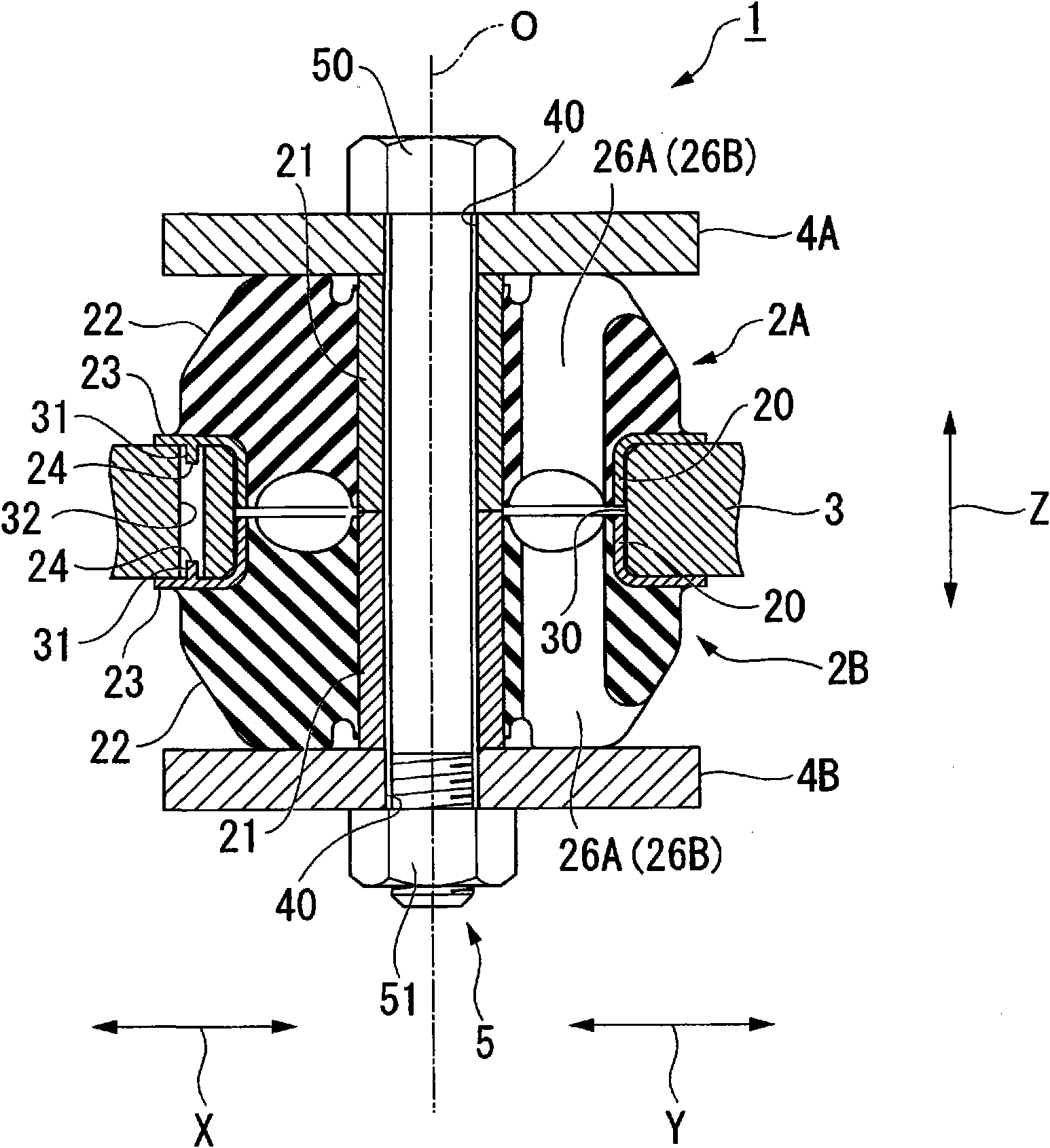
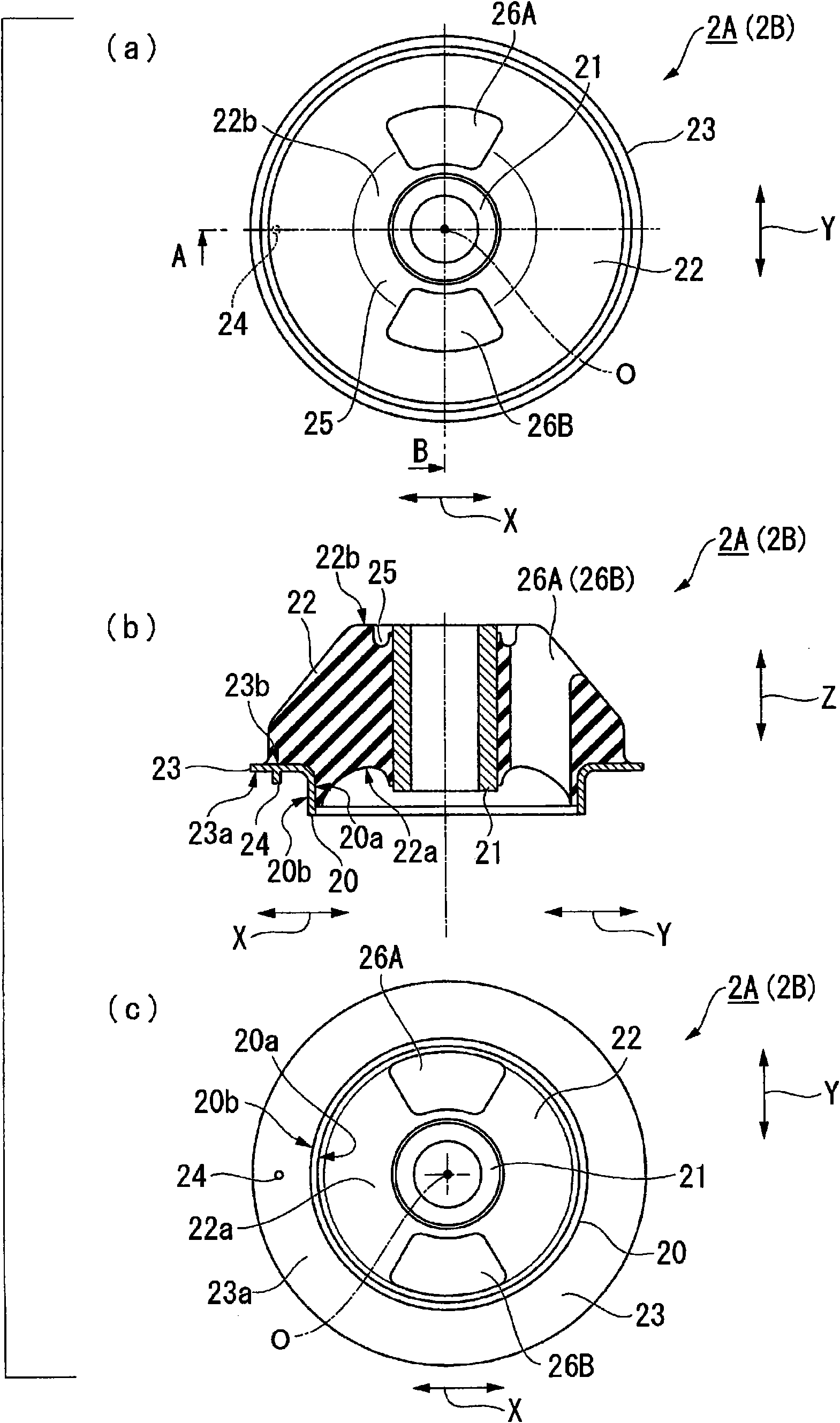
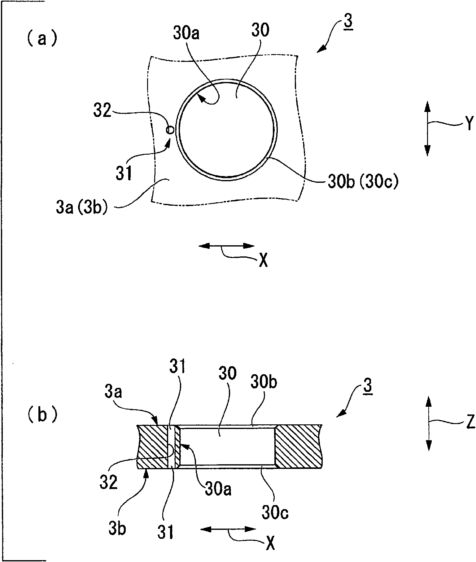
[0045] First, use Figure 1 ~ Figure 3 The anti-vibration device 1 of the first embodiment will be described.

[0046] In the following description, the direction of reference sign X (horizontal direction) in the drawings is referred to as the front-rear direction, the direction of reference sign Y (vertical direction) is referred to as the left-right direction, and the direction of reference sign Z (vertical direction) is referred to as the up-down direction. In addition, the side opposite to the other anti-vibration rubber 2B (2A) viewed from one anti-vibration rubber 2A (2B) ( figure 2 The lower side in (b)) is regarded as the inner side of the axis direction, and the opposite side ( figure 2 The upper side in (b)) is defined as the outer side in the axial direction.

[0047] figure 1 It is a sectional view of the anti-vibration device 1 of the first embodiment.

[0048] figure 2 It is a figure which shows the anti-vibration rubber 2A (2B) of the state which does no...

no. 2 Embodiment approach

[0083] Next, the anti-vibration device 101 of the second embodiment will be described. In addition, the same code|symbol is attached|subjected to the same structure as said 1st Embodiment, and the description is abbreviate|omitted.

[0084] Figure 4 It is a sectional view of the anti-vibration device 101 of the second embodiment.

[0085] Figure 5 is a diagram showing the inner cylinder side split body 110, Figure 5 (a) is a side view, Figure 5 (b) is a sectional view, Figure 5 (c) is a plan view seen from the inner side in the axial direction.

[0086] Figure 6 is a diagram showing the outer cylinder side split body 111, Figure 6 (a) is a plan view seen from the outside of the axial direction, Figure 6 (b) is a sectional view.

[0087] in addition, Figure 4 , Figure 5 of (b), Figure 6 The left half (left side of the central axis O) of (b) is a cross-sectional view in the front-rear direction, and the right half (right side of the central axis O) is a cr...


PUM


Abstract

In vibration control equipment (1) constituted by inserting the outer tube (20) of a pair of damping rubbers (2A, 2B) into the opening (30) of a bracket member (3), clamping the pair of damping rubbers (2A, 2B) by means of plate members (4A, 4B), tightening a fastening member (5) for coupling the plate members (4A, 4B), and then compressing the rubber elastic bodies (22) of the damping rubbers (2A, 2B) in the axial direction, outside diameter of the outer tube (20) before tightening the fastening member (5) is smaller than the inside diameter of the fixing hole (30), the rubber elastic bodies(22) are compression deformed by tightening the fastening member (5) and thus a bracket member (3) is clamped by means of upper and lower flanges (23), at least one of the rubber elastic bodies (22) is provided with mold cavity portions (26A, 26B) and at least one of the pair of outer tubes (20) is provided with a portion (24) for determining the circumferential position of the pair of damping rubbers (2A, 2B) relative to the bracket member (3). According to the invention, assembling work is facilitated by arranging the mold cavity portions in accordance with the direction of vibration and the production cost can be reduced.

Description

technical field [0001] The present invention relates to an anti-vibration device used as a cabin support, engine support, etc. of agricultural machinery and construction machinery. [0002] this application claims priority based on Japanese Patent Application No. 2007-095292 for which it applied in Japan on March 30, 2007, The content is used here. Background technique [0003] Generally, when a vibration generating body such as an engine is mounted on a vibration receiving body such as a body, a vibration isolator for preventing or suppressing transmission of vibration from the vibration generating body to the vibration receiving body is installed between the vibration generating body and the vibration receiving body. As this anti-vibration device, there is a sandwich type anti-vibration device constituted by a structure in which a pair of anti-vibration rubbers are sandwiched from both sides by plate members. The anti-vibration rubber is composed of a substantially cylind...

Claims


Application Information

Patent Timeline
Patent Type & Authority Applications(China)
IPC IPC(8): F16F15/08F16F1/36F16F1/38
CPCF16F3/0873F16F1/3735
Inventor 藤原敦洋
Owner BRIDGESTONE CORP
Learn More