
Inverter controller

A control device and inverter technology, applied in the direction of output power conversion device, conversion of irreversible DC power input to AC power output, conversion of AC power input to DC power output, etc., can solve discontinuous inflection point, switching action Increase and other problems, to achieve the effect of suppressing imbalance

Inactive Publication Date: 2010-02-10
NEXGEN CONTROL SYST LLC
View PDF1 Cites 26 Cited by
  • Summary
  • Abstract
  • Description
  • Claims
  • Application Information

AI Technical Summary

Problems solved by technology

[0011] Here, in the modulation waveform generated by the line voltage control PWM method, at the timing of each end of the switching pause period set at every 120°, the phase of the pause switch is switched, and a discontinuous inflection point is generated in the modulation wave of each phase , and unwanted switching action will increase the

Method used


Image

  • Inverter controller
  • Inverter controller
  • Inverter controller

Examples


Embodiment approach 1

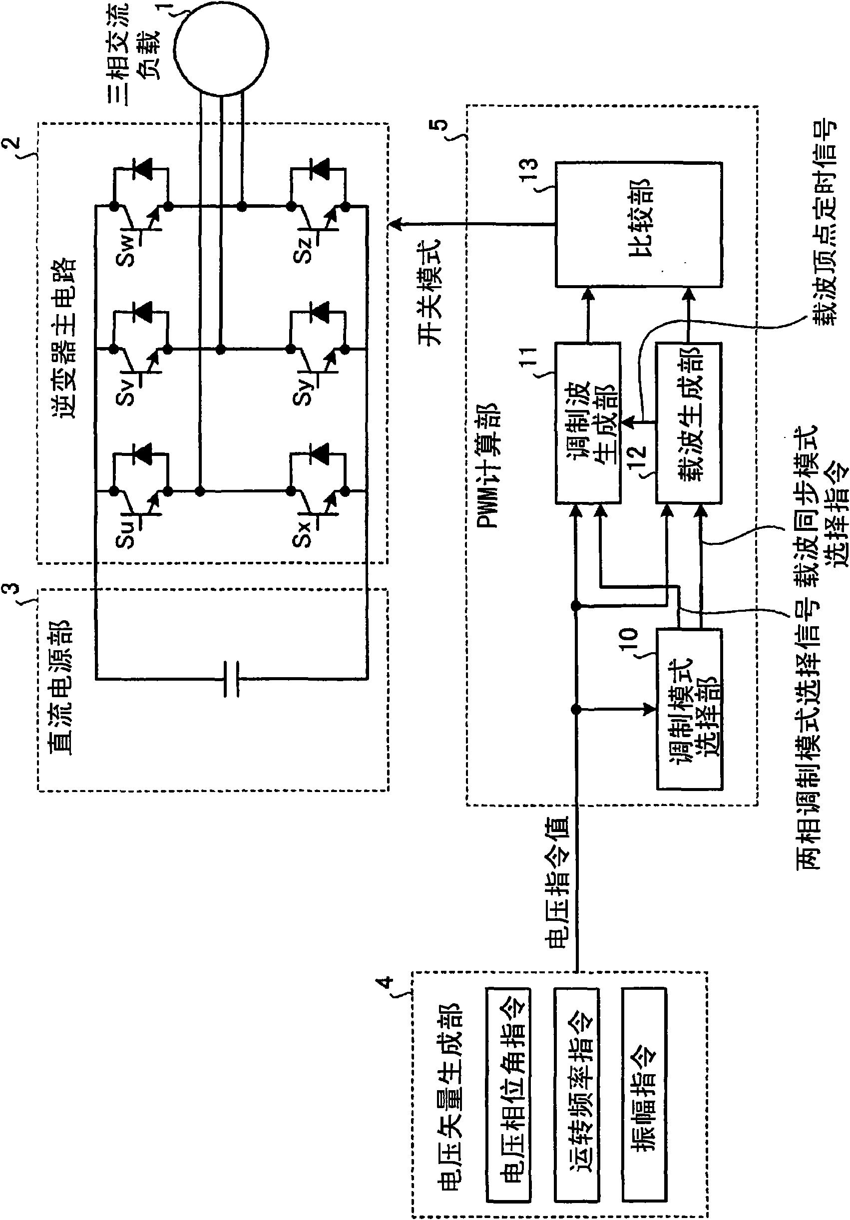
[0061] figure 1 It is a configuration diagram showing the inverter control device according to Embodiment 1 of the present invention, and shows an embodiment of the inverter control device that controls the three-phase AC load 1 .

[0062] figure 1 Among them, the inverter control device according to Embodiment 1 includes: an inverter main circuit 2 , a PWM calculation unit 5 that generates a switching pattern for controlling the inverter main circuit 2 , and generates a voltage supplied to the PWM calculation unit 5 . A voltage vector generation unit 4 of a command value. The inverter main circuit 2 constitutes a bridge circuit, in which a pair of switching parts (Su, Sv, Sw, Sx, Sy, Sz) connected in series with switching elements and diodes in antiparallel, connected to two upper and lower circuits They are respectively connected in parallel to form a three-phase part. To the DC terminal of the inverter main circuit 2, for example, a DC power supply unit 3 connected to ...

Embodiment approach 2

[0128] In Embodiment 1, when the modulation wave frequency exceeds a predetermined value, the carrier wave is set so that the carrier frequency is an integer multiple of the modulation wave frequency, thereby suppressing the phase imbalance of modulation and unnecessary power ripple. On the other hand, when using such a method, noise (mainly magnetostrictive sound) will also be generated from the inverter main circuit 2 or the three-phase AC load 1 at the switching timing of the carrier frequency, which is sometimes not suitable for attention. Use of low-noise inverters. Embodiment 2 shown below is an embodiment suitable for such an inverter in which low noise is emphasized.

[0129] Figure 15 It is a figure which shows the setting example of the carrier frequency concerning Embodiment 2. Figure 15 In this case, for example, in the region (A) of the figure, the two-phase modulation mode is appropriately selected, and the carrier frequency fc is switched at any time while m...


PUM


Abstract

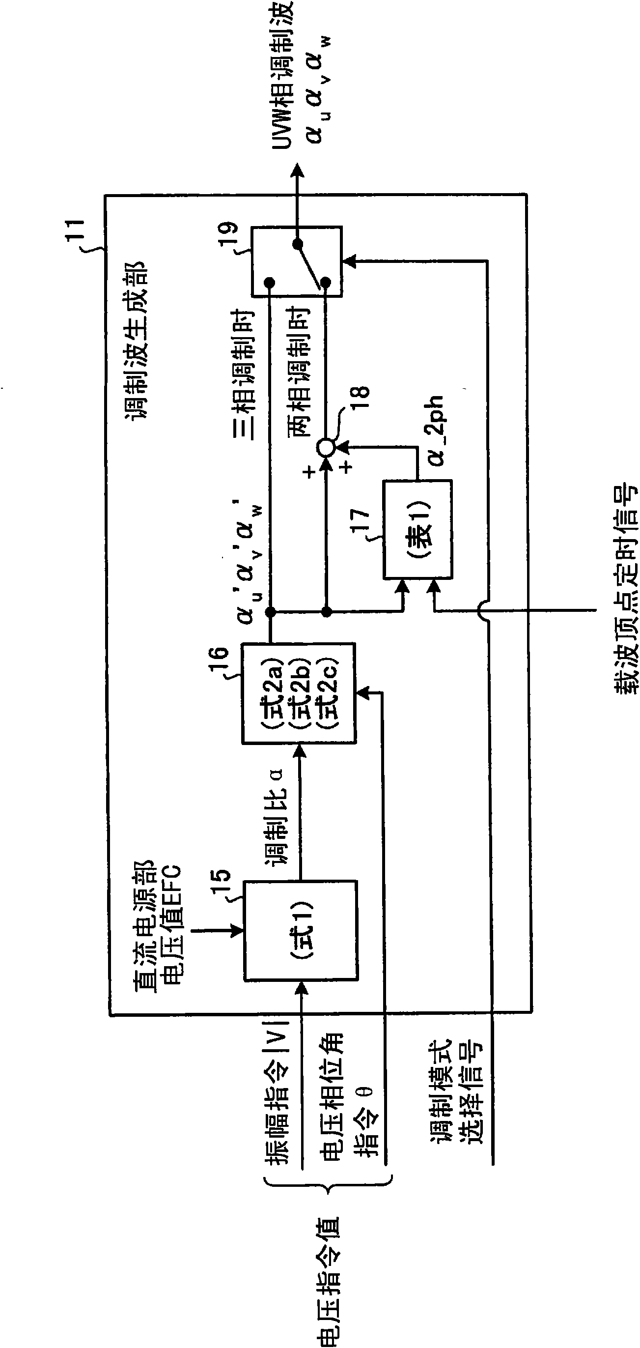
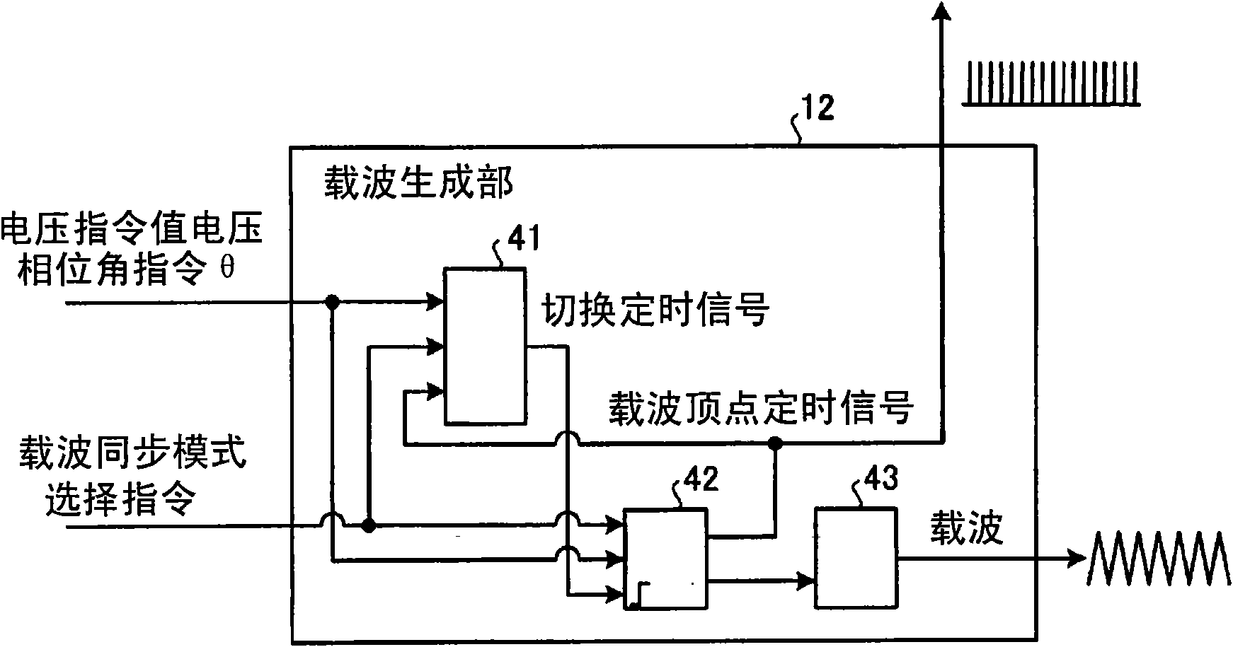
To suppress an unbalance of a dwell period in a changeover of phases in which switching is dwelled in an inverter controller. A PWM operation unit 5 includes a modulation-wave generating unit 11 that generates a modulation wave as a voltage command value to an inverter main circuit 2, a carrier-wave generating unit 12 that generates a carrier wave used as a reference for a switching command, and a comparing unit 13 that compares the modulation wave generated by the modulation-wave generating unit 11 and the carrier wave generated by the carrier-wave generating unit 12. During an operation in a two-phase modulation mode in which switching of any one of three phases configuring the inverter main circuit 2 is dwelled, the PWM operation unit 5 controls the carrier-wave generating unit 12 to set a carrier wave frequency to an integral multiple of a modulation wave frequency.

Description

technical field [0001] The present invention relates to an inverter control device for controlling an inverter for driving three-phase AC equipment such as a motor. Background technique [0002] In an inverter main circuit composed of bridge-connected semiconductor elements included in the inverter, switching loss occurs in the semiconductor elements due to switching control by PWM (Pulse Width Modulation). On the other hand, the main circuit of the inverter is provided with a cooler such as a cooling fin or a fan so that the heat generated by the loss does not damage the semiconductor element. Considering that the small size can increase the value of the inverter product, it is necessary to reduce the size of the cooler, but in order to achieve a small size, it is required to reduce the switching loss. [0003] Here, the following method can be exemplified as a conventional control method for realizing reduction of switching loss. [0004] (1) Reduce the carrier frequency...

Claims


Application Information

Patent Timeline
Patent Type & Authority Applications(China)
IPC IPC(8): H02M7/48
CPCH02M7/5395H02M7/53873H02M2007/53876H02M7/53876
Inventor 山崎尚德
Owner NEXGEN CONTROL SYST LLC
Learn More