

Ac power supply device
A technology of AC power supply and power storage device, which is applied in the direction of circuit device, battery circuit device, emergency power supply arrangement, etc. It can solve the problems that parallel operation of uninterrupted AC power supply devices cannot be easily realized, and achieve the effect of suppressing current imbalance
- Summary
- Abstract
- Description
- Claims
- Application Information
AI Technical Summary
Problems solved by technology
Method used
Image

Examples
Embodiment 1
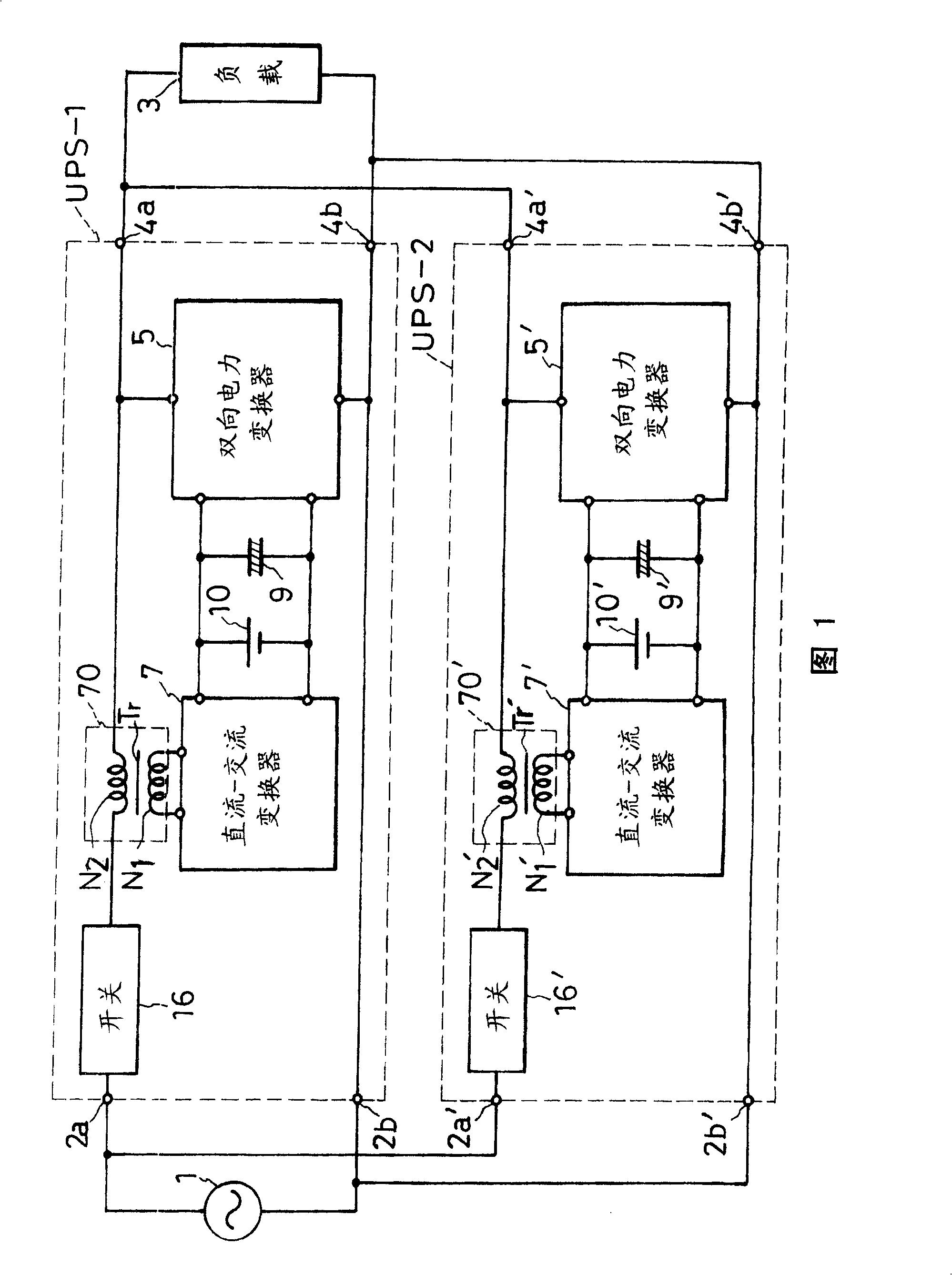
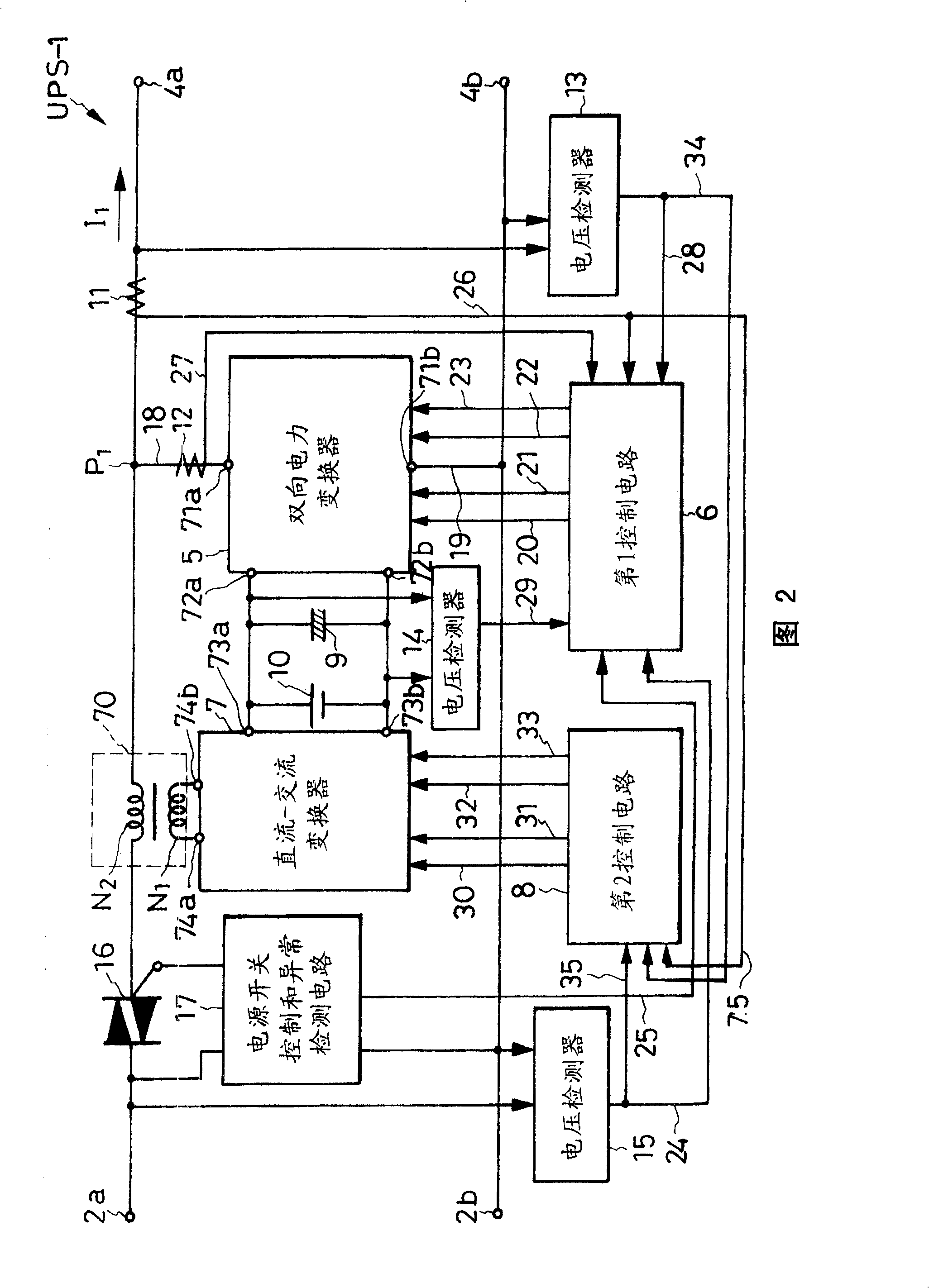
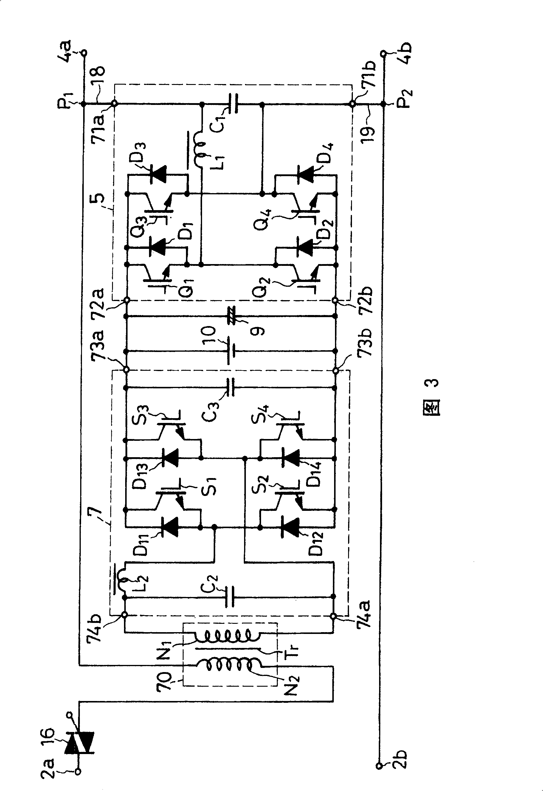
[0053] The main circuit of the AC power supply device according to Embodiment 1 of the present invention is composed of a parallel connection circuit of first and second uninterruptible AC power supply devices UPS-1 and UPS-2 as shown in FIG. 1 . Although in Fig. 1 there are two uninterruptible AC power supply units UPS-1 and UPS-2 connected in parallel, of course there may be more than or equal to three units or only one unit. The first and second uninterruptible AC power supply units UPS-1 and UPS-2 have the same configuration. Therefore, the first uninterruptible AC power supply unit UPS-1 will be described in detail, and the detailed description of the second uninterruptible AC power supply unit UPS-2 will be omitted. In addition, in FIG. 1, the same reference numerals are attached to the same parts. In order to distinguish the first and second uninterruptible AC power supply units UPS-1 and UPS-2, the reference numerals for each part of the second uninterruptible AC power...
Embodiment 2
[0122] Next, referring to FIG. 14, the AC power supply unit of the second embodiment will be described. In Figures 14 to 19, for the same as Figures 1 to 19 Figure 13 Substantially the same parts are assigned the same symbols, and description thereof will be omitted. In addition, in the description of FIGS. 14 to 19 , refer to FIGS. 1 to 19 as necessary. Figure 13 .
[0123] The AC power supply device of embodiment 2 transforms the main circuits of the first and second uninterruptible AC power supply devices UPS-1 and UPS-2 of embodiment 1 in Fig. 1, and has the same features as the power supply device of embodiment 1 structure. In FIG. 14 , the main circuit of the first uninterruptible AC power supply unit in the AC power supply unit according to the second embodiment is shown as in FIG. 3 . In the main circuit of the first uninterruptible AC power supply device of the AC power supply device of the embodiment 2 shown in FIG. It has the same structure as the main circui...
Embodiment 3
[0127] FIG. 15 shows the main circuit of the first uninterruptible AC power supply unit of the AC power supply unit according to the third embodiment. The main circuit of the first uninterruptible AC power supply device of Embodiment 3 transforms the DC-AC converter 7 of Embodiment 1 shown in FIG. Unit 70a; otherwise, it has the same structure as in FIG. 3 .
[0128] The DC-AC converter 7a of Fig. 15 is composed of the first and second conversion switches S1, S2, the first and second parallel diodes D11, D12, the first and second conversion capacitors C11, C12, and the second filter power The reactance coil L2 and the capacitor C2 are used for the second filter. In addition, the voltage adjustment unit 70a is constituted by an autotransformer Tr' having a coil Ns.
[0129] A series circuit of the first and second conversion capacitors C11 and C12 is connected in parallel to the capacitor 9 and the storage battery 10 . The coil Ns is connected between the mutual connection p...
PUM
 Abstract
Description
Claims
Application Information