
Method and special device for automatically identifying suction/discharge mechanism range of electronic pipette

An automatic identification and pipette technology, applied in the direction of measuring tube/pipette, etc., can solve the problems of troublesome operation, wrong operation, and complicated switching steps of operation mode, so as to save time and avoid wrong operation.

Inactive Publication Date: 2010-02-17
杭州柯诺医疗科技有限公司
View PDF0 Cites 4 Cited by
  • Summary
  • Abstract
  • Description
  • Claims
  • Application Information

AI Technical Summary

Problems solved by technology

[0004] One of the purposes of the present invention is to solve the shortcomings of the electronic pipette, such as complicated operation mode switching steps, troublesome operation, and easy operation errors, after the electronic pipette is replaced with different volume suction / discharge mechanisms in actual operation, and provides A method for automatically identifying the range of the suction / discharge mechanism for electronic pipettes

Method used


Image

  • Method and special device for automatically identifying suction/discharge mechanism range of electronic pipette
  • Method and special device for automatically identifying suction/discharge mechanism range of electronic pipette

Examples


specific Embodiment 1

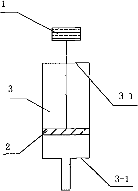
[0028] figure 1 Structure Cost Example 1.

[0029] The inner cavity of the electronic pipette is provided with a control unit, a stepping drive unit, a reciprocating movement unit and a reciprocating movement termination point; the reciprocation movement unit moves within the range limited by the reciprocation movement termination point; the signal output terminal of the detection and control unit is connected The control signal input end of the stepping drive unit, the signal output end of the stepping drive unit are connected to the signal input end of the reciprocating motion unit, the feedback signal output end of the stepping drive unit is connected to the feedback signal input end of the detection and control unit.

[0030] In this embodiment, the detection and control unit of the electronic pipette includes a detection controller; a stepping driver and a stepping motor form a stepping drive unit; a piston and a piston cylinder form a reciprocating movement unit; Moveme...

specific Embodiment 2

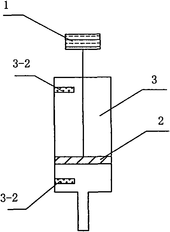
[0033] Such as figure 2 As shown, the characteristics of this embodiment are: two blocking parts 3-2 are installed on the inner walls at both ends of the piston cylinder 3 as the positive termination point and the reverse termination point of the reciprocating motion of the piston 2; the blocking parts at both ends of the piston cylinder The space between 3-2 is the range of the piston cylinder. All the other are identical with specific embodiment 1.


PUM


Abstract

The invention discloses a method and a special device for automatically identifying suction / discharge mechanism range of an electronic pipette. A cavity of the electronic pipette is provided with a checking control unit, a stepping drive unit, a reciprocating motion unit and a reciprocating terminating point. Whether the suction / discharge mechanism range of the electronic pipette is the one required by users can be effectively judged by detecting movement distance and movement time of a piston through the inside computer programming, without an additional detecting instrument, which saves thetime of users.

Description

technical field [0001] The invention relates to a method and a special device for automatically identifying the range of the suction / discharge mechanism of the electronic pipette, which can automatically identify the range of the suction / discharge mechanism of the electronic pipette. The utility model belongs to the field of electronic measuring instruments for accurately transferring liquids. Background technique [0002] Electronic pipettes are used to precisely transfer a certain volume of liquid samples or reagents. An electronic pipette is usually composed of a detection control system and a suction / discharge system; among them, the detection control system is composed of a stepper motor, a stepper driver, a motor detection controller, etc., and the suction / discharge system is composed of a piston, a piston cylinder and a disposable Suction nozzle composition; the stepping motor in the control system of the detection control system drives one or more pistons in the suc...

Claims


Application Information

Patent Timeline
IPC IPC(8): B01L3/02
Inventor 吕志荣郑得胜史龙
Owner 杭州柯诺医疗科技有限公司
Learn More