Complete-disc brake
A brake and full-disk technology, applied in the direction of brake types, hydraulic brakes, brake components, etc., can solve problems such as troublesome and inconvenient use, and achieve the effects of small structural changes, low manufacturing costs, and easy popularization and use
- Summary
- Abstract
- Description
- Claims
- Application Information
AI Technical Summary
Problems solved by technology
Method used
Image

Examples
Embodiment 1
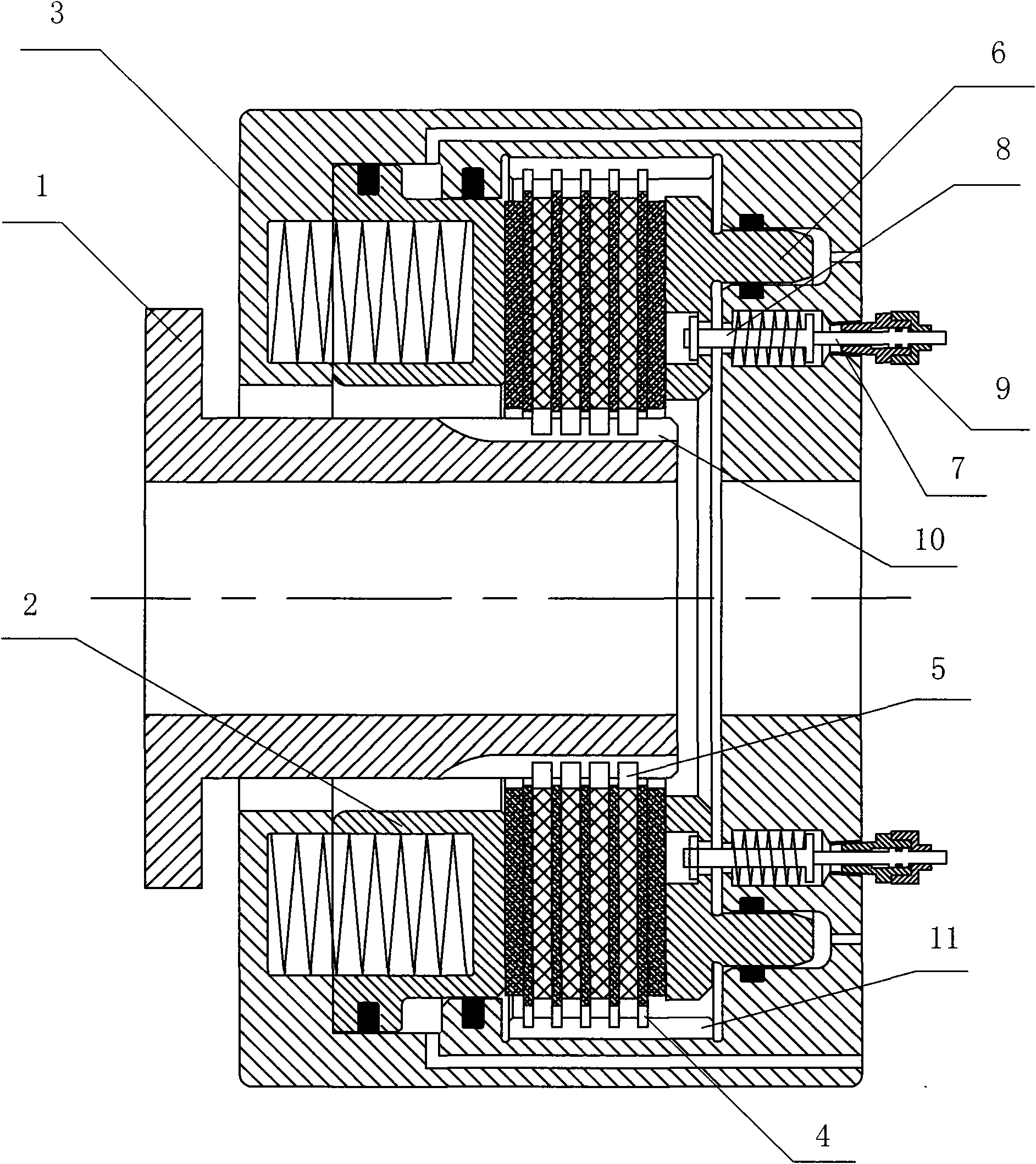
[0025] Embodiment one: see figure 1 As shown, a full disc brake includes a wheel 1, a housing 3, a friction plate assembly and a piston assembly, the friction plate assembly is composed of 4 rotating friction plates 5 and 5 sliding friction plates 4, and the rotating friction plates 5 and The sliding friction plates 4 are arranged at intervals, the rotating friction plates 5 are connected to the wheel 1 through the spline groove 10, the sliding friction plates 4 are installed on the housing 3 through the annular key groove 11, and the friction plate assemblies have The degree of freedom of axial movement, the piston assembly is located in the housing 3, respectively composed of the parking brake piston 2 on the left side of the friction plate assembly and the service brake piston 6 on the right side, and one end of the pistons on both sides is pressed against the On the friction plate assembly, a measuring rod 7 is inserted in the housing 3 corresponding to the return rod 8 of...
Embodiment 2
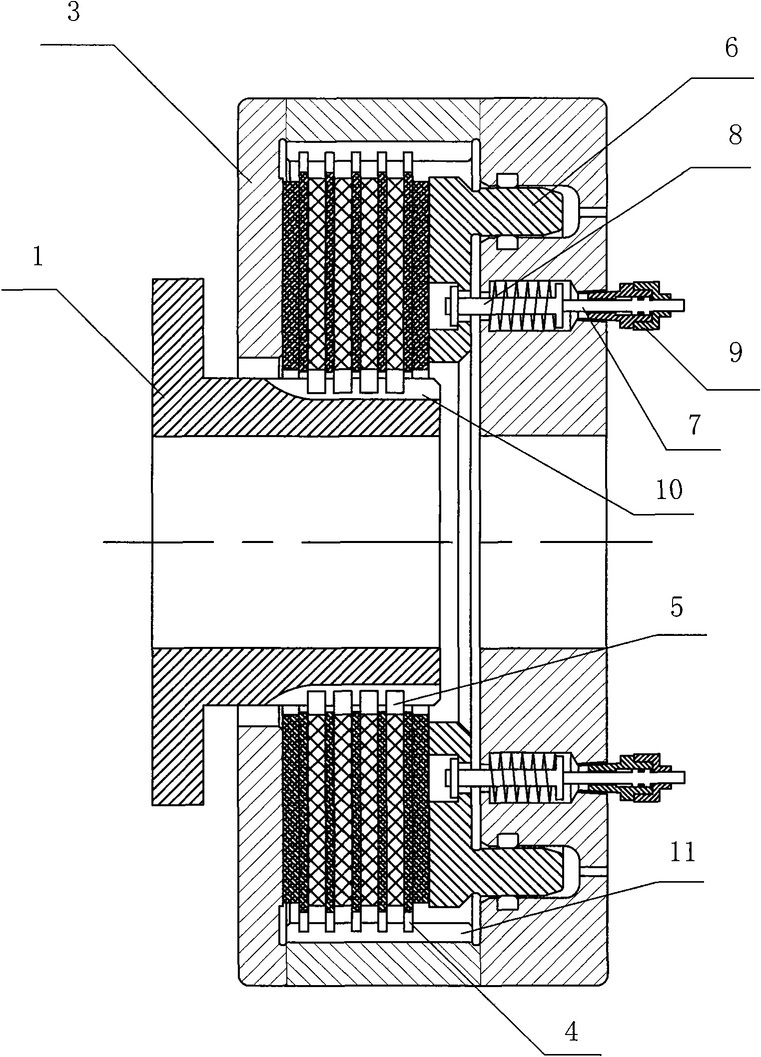
[0028] Embodiment 2: This embodiment is similar to Embodiment 1, except that the piston assembly includes a service brake piston 6 located on the right side of the friction plate assembly, and the left side of the friction plate assembly is against the housing 3 . The inner end of the measuring rod 7 is connected with the return rod 8 on the service brake piston 6 and moves axially together with the return rod 8 . The outer end of the measuring rod 7 is provided with a fixed value mark, and the friction plate assembly needs to be replaced when the measurement reaches the mark.
[0029] see figure 2 As shown: the wheel 1 rotates around the central axis, the wheel 1 is equipped with a rotating friction plate 5, the rotating friction plate can slide axially on the wheel 1, and the rotating friction plate 5 rotates with the wheel at the same time. The housing 3 is fixed on the bridge, and the sliding friction plate 4 is installed on the housing 3 and can slide axially on the hou...
Embodiment 3
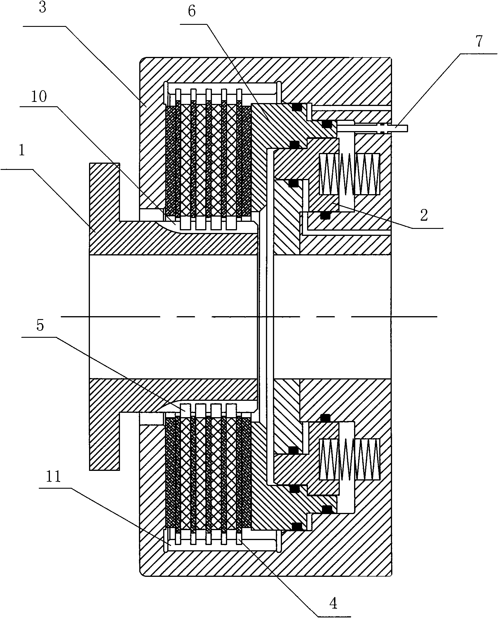
[0031] Embodiment 3: This embodiment is similar to Embodiment 1, the difference is that the piston assembly includes two groups of service brake piston 6 and parking brake piston 2, both of which are arranged on the right side of the friction plate assembly, and the friction plate assembly The left side is against the casing 3 . The inner end of the measuring rod 7 is connected to the service brake piston 6 , and a sealing structure is provided between the service brake piston 6 and the housing 3 to seal the inner cavity of the housing 3 . At the same time, an annular groove can also be provided on the measuring rod, and a sealing ring can be arranged in the annular groove to form a seal with the housing insertion hole.
[0032] see image 3 As shown, the wheel 1 rotates around the central axis, and the wheel 1 is equipped with a rotating friction plate 5, which can slide axially on the wheel 1, and the rotating friction plate 5 rotates with the wheel 1 at the same time. Hou...
PUM
 Abstract
Description
Claims
Application Information
 - Generate Ideas
- Intellectual Property
- Life Sciences
- Materials
- Tech Scout
- Unparalleled Data Quality
- Higher Quality Content
- 60% Fewer Hallucinations
Browse by: Latest US Patents, China's latest patents, Technical Efficacy Thesaurus, Application Domain, Technology Topic, Popular Technical Reports.
© 2025 PatSnap. All rights reserved.Legal|Privacy policy|Modern Slavery Act Transparency Statement|Sitemap|About US| Contact US: help@patsnap.com