On-load switch hanger of transformer

A technology for transformers and switches, applied in the field of transformer on-load switch spreaders, can solve the problems of inability to lift the switch oil chamber, cumbersome switch assembly, and damage to the switch, and achieve the effect of changing the conventional installation process, shortening the assembly time, and avoiding bumps.

Inactive Publication Date: 2011-10-05
CHINESE ELECTRICAL EQUIP GRP CO LTD
View PDF0 Cites 0 Cited by
  • Summary
  • Abstract
  • Description
  • Claims
  • Application Information

AI Technical Summary

Problems solved by technology

[0003] The assembly of the switch is cumbersome. The switching switch is lifted out and then hoisted in. Every link must be careful and careful, and the slightest bump will cause the switch to be damaged or even scrapped.
If the changeover switch in the oil chamber is not hoisted out, the switch manufacturer’s own sling cannot be used, and the switch oil chamber cannot be hoisted, so this procedure must be followed every time

Method used


Image

  • On-load switch hanger of transformer
  • On-load switch hanger of transformer
  • On-load switch hanger of transformer

Examples


Embodiment Construction

[0019] The specific implementation manners of the present invention will be further described in detail below in conjunction with the accompanying drawings.

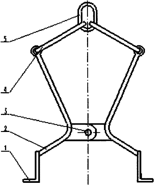
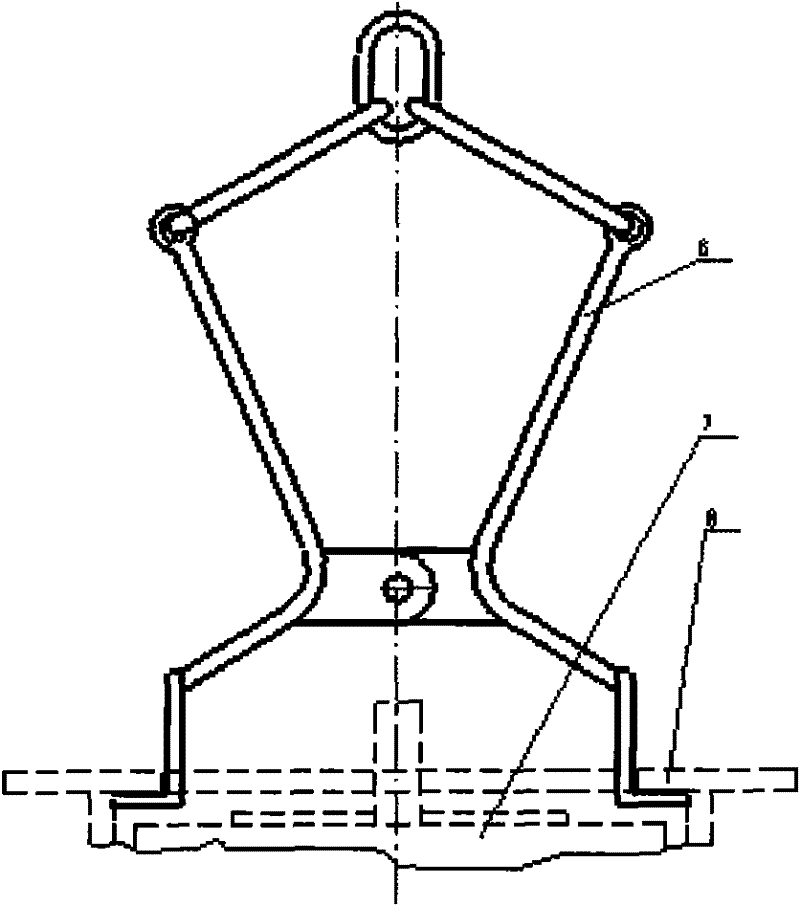
[0020] Such as figure 2 As shown, the transformer on-load switch hanger of the present invention includes a support foot 1, a connecting rod 2, a connecting member 4, and a lifting ring 5. The connecting rod 2 is two curved rods hinged at the bending position, each The lower ends of the connecting rods 2 are fixedly connected with supporting feet 1 respectively, and the stress surface of the supporting feet 1 is processed into a shape suitable for the bottom surface of the switch flange. The upper end is movably connected, and the other end is movably connected together with suspension ring 5.

[0021] Such as figure 2 As shown, the connecting rod 2 of the present invention is a V-shaped or L-shaped curved rod, and a plate can also be welded at the bending position of the connecting rod 2, and the two connecting rods...


PUM


Abstract

The invention provides an on-load switch hanger of a transformer, aiming at the deficiencies of complex working procedure and difficult realization of the original switch own hanger during the assembly process of the transformer. The hanger comprises a lifting ring, a support leg and a support leg regulating mechanism arranged between the lifting ring and the support leg, wherein the support leg regulating mechanism comprises two symmetrically arranged connecting rods which are bent and are hinged at a bent position, and the upper end of each connecting rod is movably connected with the lifting ring through a connecting mechanism, and the lower end is fixedly connected with the support leg. The invention solves the problem that an internal toggle switch of the on-load transformer switch can not be installed without lifting out the internal toggle switch and avoids the difficulties that the toggle switch is knocked when being lifted out and lifted in and the assembly precision demand is high, thereby changing the routine installation procedure of the on-load switch, reducing the assembly working procedures and improving the productivity. The hanger has the advantages of simple structure, small volume, light weight, convenient operation, flexible moving and the like, therefore facilitating the use of production fields and job sites.

Description

technical field [0001] The invention relates to a transformer on-load switch hanger, which belongs to the technical field of transformer tooling equipment manufacturing. Background technique [0002] After the body of the conventional transformer on-load tap changer is installed, before vacuum drying, the diverter switch in the switch oil chamber is usually hoisted out first, then the oil-saving tank cover is installed, and then the diverter switch oil chamber is lifted by the special lifting tool provided by the manufacturer. Lift to connect with the switch flange outside the upper fuel tank, and finally lift the diverter switch into the switch oil chamber, and use a special tool to move the switch to a fixed position, and connect it to the switch flange through bolts. [0003] The assembly of the switch is cumbersome. The switch must be hoisted out and then hoisted in again. Care must be taken in every link, and the switch must not be sloppy. A slight bump will cause the s...

Claims


Application Information

Patent Timeline
Patent Type & Authority Patents(China)
IPC IPC(8): H01F41/00H01F29/04H01F27/06
Inventor 张永华
Owner CHINESE ELECTRICAL EQUIP GRP CO LTD
Why Eureka
Try Eureka