Simplified controllable rectifying device

A rectifier, full-bridge rectifier technology, applied in the direction of converting irreversible AC power input to DC power output, etc., can solve problems such as high cost, high requirements for thyristor, and complex circuit, and achieve simple triggering, simplified triggering of transformers, simple structure

Inactive Publication Date: 2010-02-17
CGN DASHENG ELECTRON ACCELERATOR TECH
View PDF0 Cites 0 Cited by
  • Summary
  • Abstract
  • Description
  • Claims
  • Application Information

AI Technical Summary

Benefits of technology

This technology uses a special type called a transistor that works like an electronic switch with two main parts: one part contains certain atoms (called amulets) which are charged or discharged by electric current flowing through them. These charges change their state when they come into contact with another object - this process can be controlled electronically without any moving components involved.

Problems solved by technology

This patented problem with current control circuits involves having many expensive components that are difficult or complex to use due to their requirement on transistors.

Method used


Image

  • Simplified controllable rectifying device
  • Simplified controllable rectifying device
  • Simplified controllable rectifying device

Examples


Embodiment Construction

[0011] Below in conjunction with accompanying drawing, the technical scheme of invention is described in detail:

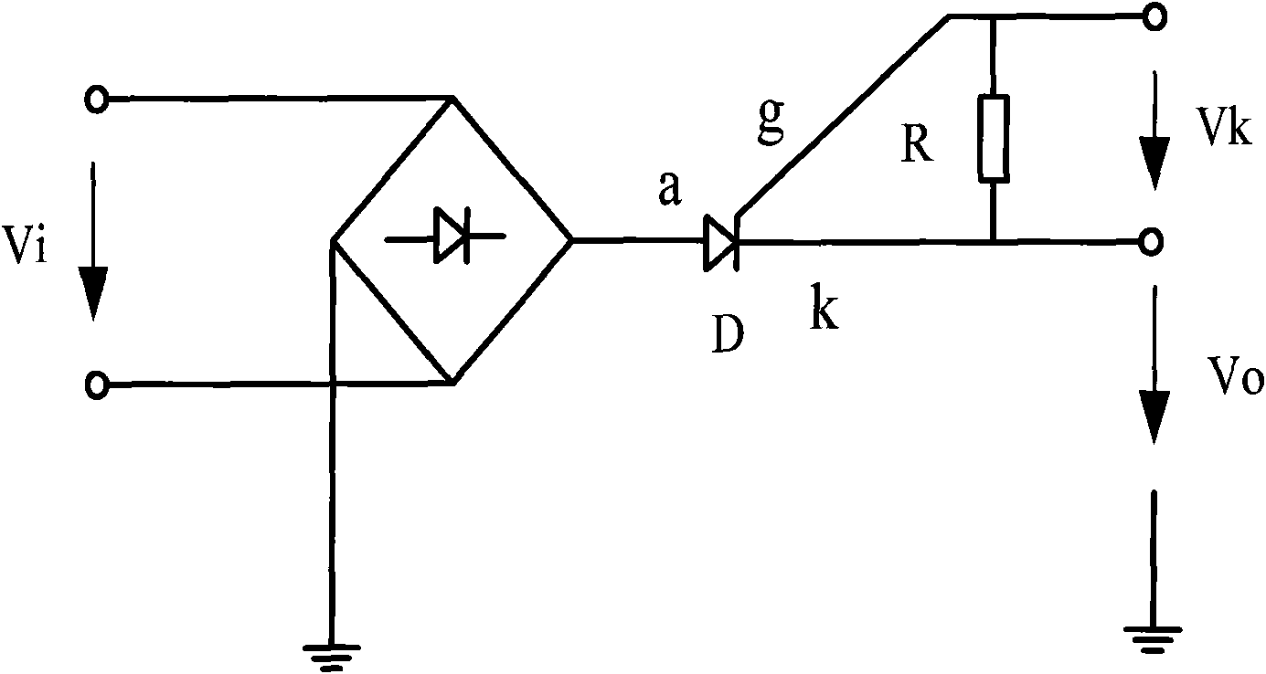
[0012] Such as figure 1 As shown, the simplified controllable rectification device is characterized in that it includes a full-bridge rectifier, a thyristor and a resistor, wherein the input terminal of the full-bridge rectifier is connected to an external power supply, and one output terminal is grounded and the other output terminal is connected to the anode of the thyristor. , the resistor R is connected between the thyristor control pole and the cathode.

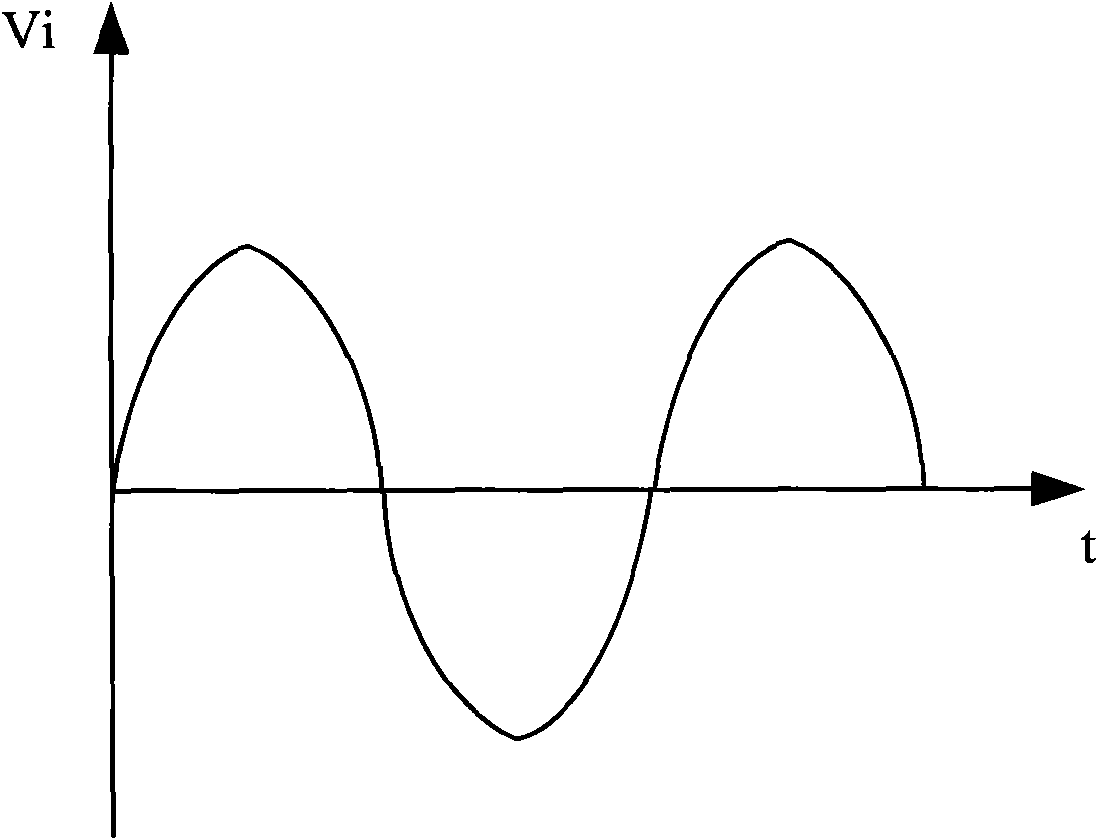
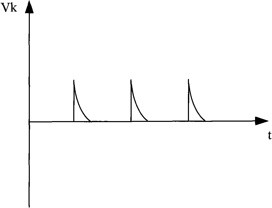
[0013] Such as Figure 2 to Figure 4 As shown in the waveform diagrams of each point, it can be seen that the triggering of the present invention is stable and stable.


PUM


Abstract

The invention discloses a simplified controllable rectifying device, comprising a full-bridge rectifier, a controllable silicon and a resistance, wherein the input end of the full-bridge rectifier isconnected with an external power supply, one output end thereof is grounded, and the other output end thereof is serially connected with the controllable silicon, and then the two output ends are respectively connected with two ends of the resistance. The simplified controllable rectifying device has simple structure and only adopts one piece of the controllable silicon, the triggering is simple,and a triggered transformer is simplified.

Description


Claims


Application Information

Patent Timeline
Owner CGN DASHENG ELECTRON ACCELERATOR TECH
Why Eureka
Try Eureka