Vehicle, and control method and control apparatus for an automatic transmission

A technology of automatic transmission and control equipment, which is used in transmission control, mechanical equipment, components with teeth, etc., to prevent excessive inertial force of rotating parts and reduce impact.

Inactive Publication Date: 2010-02-17
TOYOTA JIDOSHA KK
View PDF4 Cites 3 Cited by
  • Summary
  • Abstract
  • Description
  • Claims
  • Application Information

AI Technical Summary

Problems solved by technology

This will create a shift delay

Method used


Image

  • Vehicle, and control method and control apparatus for an automatic transmission
  • Vehicle, and control method and control apparatus for an automatic transmission
  • Vehicle, and control method and control apparatus for an automatic transmission

Examples


Embodiment Construction

[0031] Hereinafter, an embodiment of the present invention will be described with reference to the accompanying drawings. In the following description, the same elements are denoted by the same reference numerals. Their names and functions are also the same. Therefore, detailed description will not be repeated.

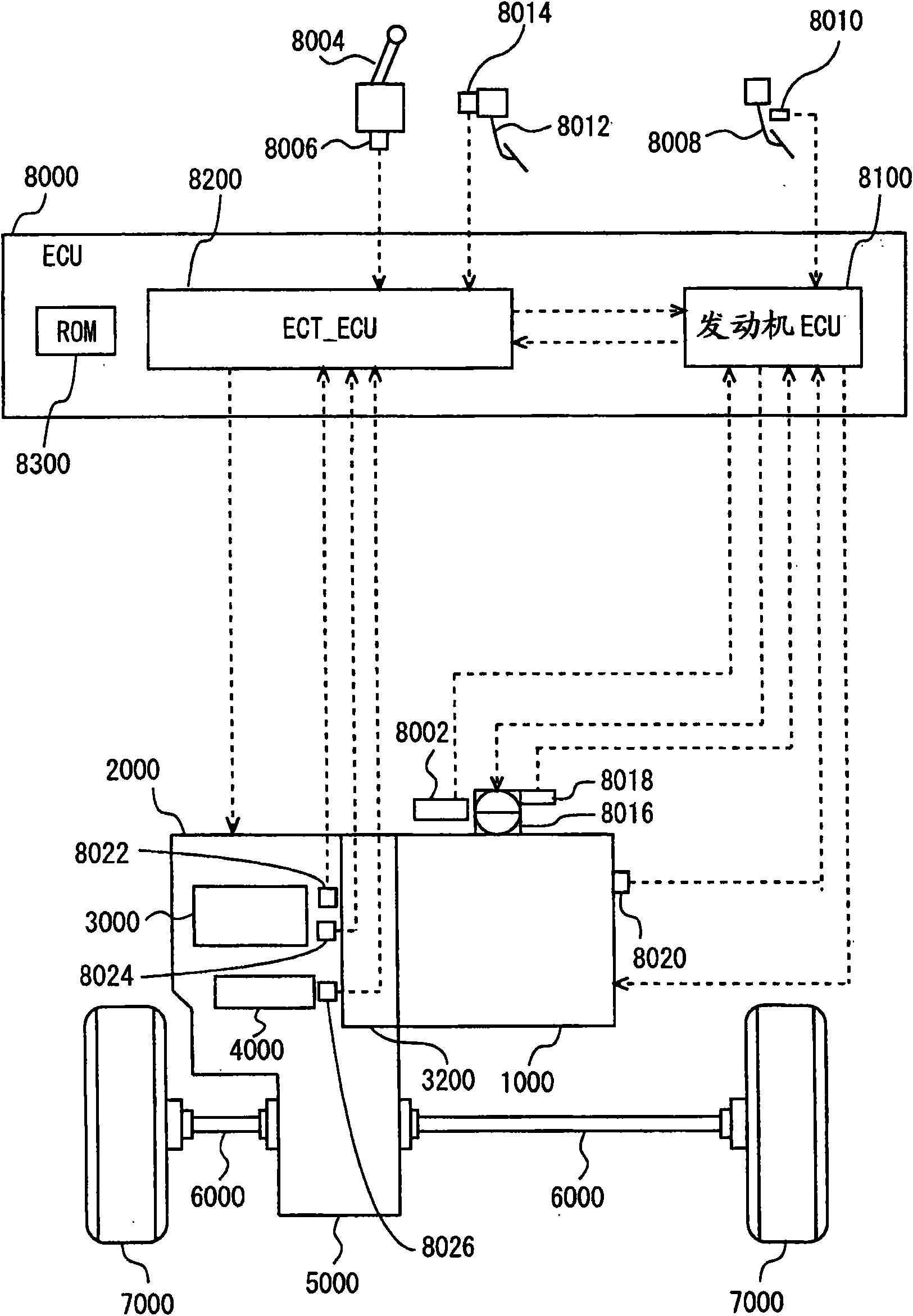
[0032] will refer to figure 1 A vehicle including a control device according to an embodiment of the present invention is described. The vehicle is an FF (Front Engine Front Drive) vehicle. But not limited to FF vehicles.

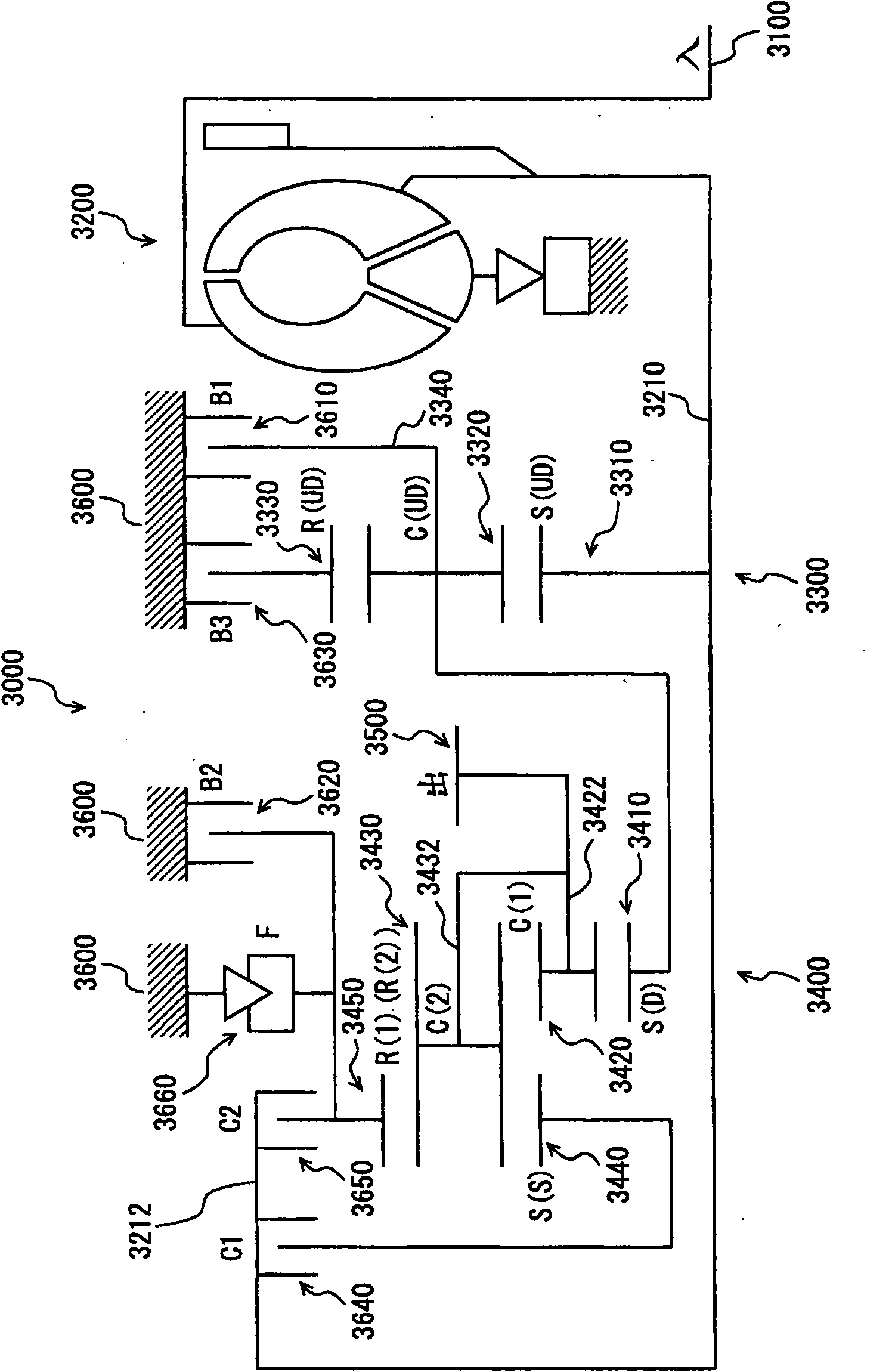
[0033] The vehicle includes an engine 1000, an automatic transmission 2000, a planetary gear unit 3000 constituting a part of the automatic transmission 2000, an oil pressure circuit 4000 constituting a part of the automatic transmission 2000, a differential gear 5000, a drive shaft 6000, front wheels 7000, and an ECU (electronic control unit) 8000. The control device is realized in the present embodiment, for example, by executing a program ...


PUM


Abstract

An ECU executes a program including the steps of: if downshift from a fifth gear implemented when a B3 brake and a C2 clutch both engage to a second gear implemented when a C1 clutch and a B1 brake both engage is done, or downshift from a sixth gear implemented when the B1 brake and the C2 clutch both engage to a third gear implemented when the C1 clutch and the B3 brake both engage is done (YES at S100), disengaging a frictional engagement element other than the C2 clutch, i.e., the B3 brake or the B1 brake (S104); and decreasing an engagement pressure that is applied to the C2 clutch to a reference value of target engagement pressure (S106).

Description

technical field [0001] The present invention relates to a vehicle and a control method and control apparatus for an automatic transmission, and more particularly to a technique applied to control an engaging element for realizing a gear position. Background technique [0002] There is conventionally known an automatic transmission that changes a combination of clutches, brakes, and other similar engaging elements to another combination for shifting gears. Such an automatic transmission may be required to shift from a gear position achieved by engaging any two of a plurality of engaging elements to a gear position achieved by engaging another different two of the plurality of engaging elements. [0003] Japanese Patent Application Laid-Open No. 2002-195401 discloses a shift control device for an automatic transmission that requires four engagement elements to actuate to shift from first gear to second gear, when the first engagement element and the second The first gear is o...

Claims


Application Information

Patent Timeline
Patent Type & Authority Applications(China)
IPC IPC(8): F16H61/06F16H61/686F16H59/42F16H59/48F16H61/04F16H61/68F16H61/684
CPCF16H2061/0451F16H61/06F16H2306/14F16H2061/0455F16H61/04
Inventor 福代英司大岛康嗣
Owner TOYOTA JIDOSHA KK
Why Eureka
Try Eureka