Engine control unit, engine control system and engine control method

a technology of engine control and control system, which is applied in the direction of electric control, engine starters, machines/engines, etc., can solve the problems of engine failure, engine stop running, and engine failure, and achieve the effect of increasing the inertial force of the engine, ensuring safety, and increasing reliability

Active Publication Date: 2013-07-18
SHINDENGEN ELECTRIC MFG CO LTD
View PDF13 Cites 2 Cited by
  • Summary
  • Abstract
  • Description
  • Claims
  • Application Information

AI Technical Summary

Benefits of technology

[0108]From this state, the engine can be run in the forward direction, thereby increasing the inertial force of the engine and starting the engine with higher reliability.
[0109]That is, the engine control unit according to the aspect of the present invention can start the engine with higher reliability.

Problems solved by technology

If the resistive force to the rotation is too high, the engine may stop running immediately before the top dead center of the cylinder in the compression stroke and fail to start.
In a warm environment, in particular, the compression pressure increases significantly, so that the start failure is likely to occur.

Method used


Image

  • Engine control unit, engine control system and engine control method
  • Engine control unit, engine control system and engine control method
  • Engine control unit, engine control system and engine control method

Examples


embodiment 1

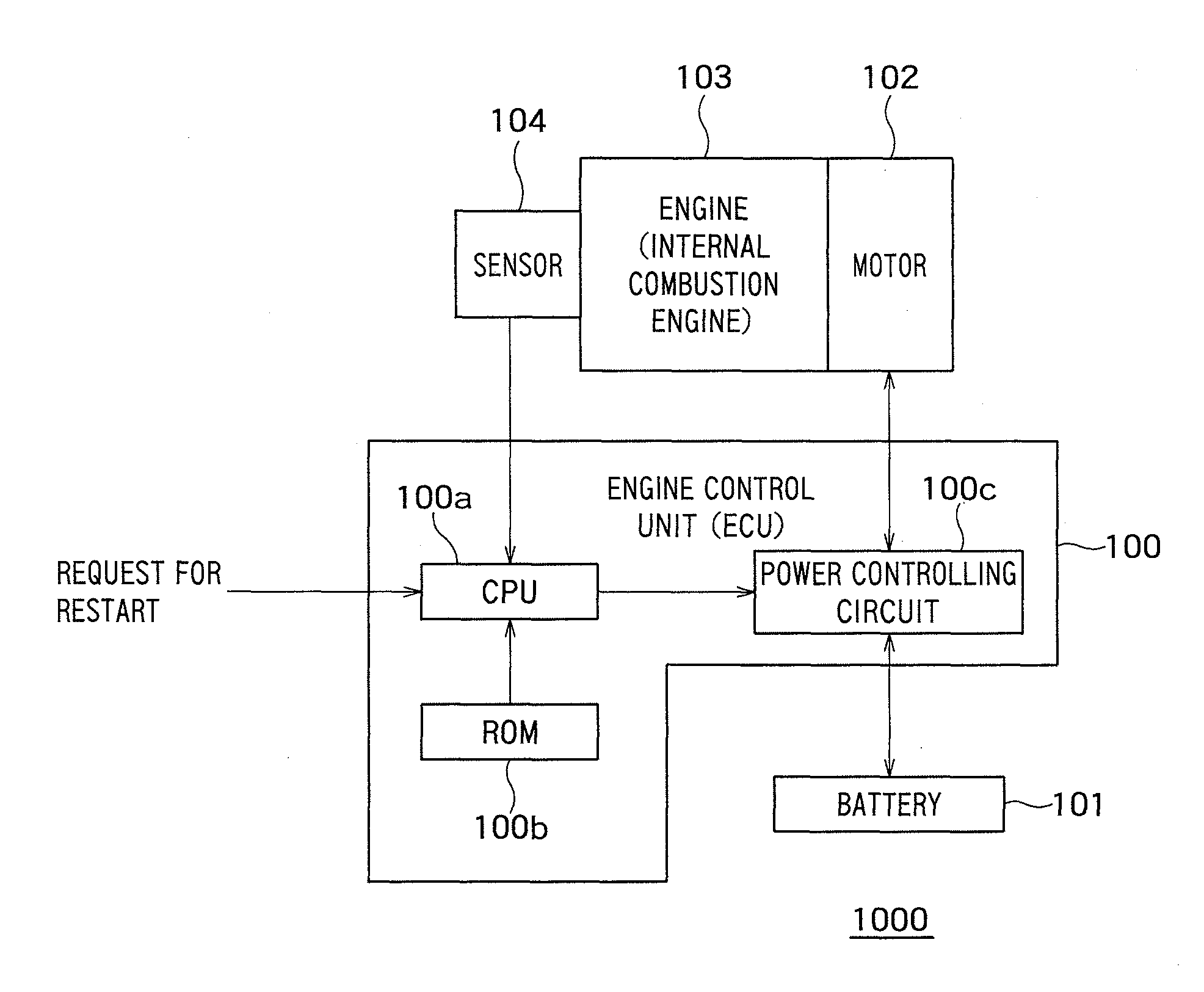
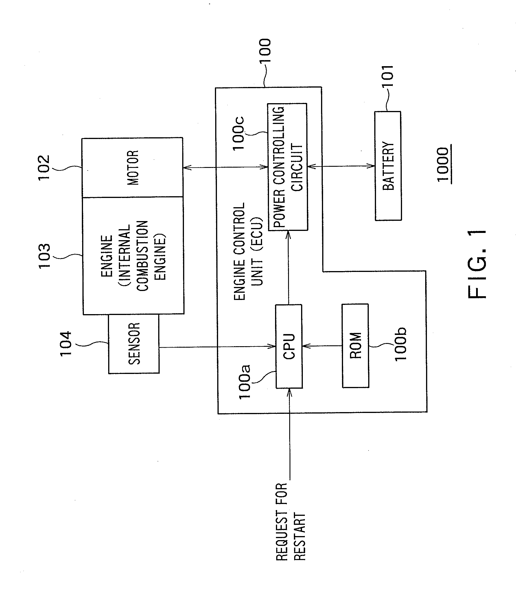
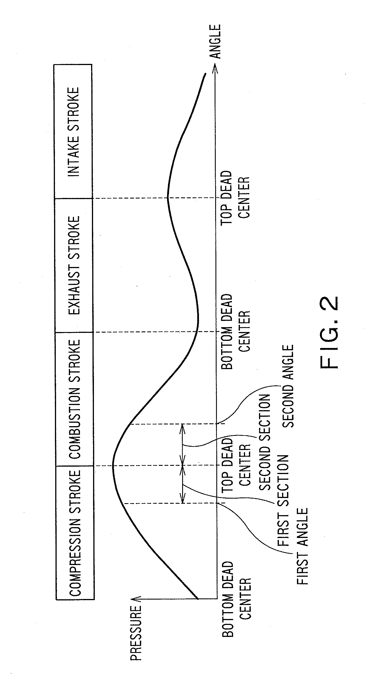
[0116]FIG. 1 is a diagram showing an example of a configuration of an engine control system 1000 according to an embodiment 1 of the present invention, which is an aspect of the present invention. FIG. 2 is a diagram showing an example of a relationship between each stroke (crank angle) and the pressure of a cylinder of an engine 103 of the engine control system 1000 shown in FIG. 1.

[0117]As shown in FIG. 1, the engine control system 1000 that controls driving of the engine has an engine control unit (ECU) 100, a battery 101, a motor 102, an engine (internal combustion engine) 103, and a sensor 104.

[0118]In this embodiment, the engine 103 is a four-stroke engine, for example. Therefore, as shown in FIG. 2, the status of the engine 103 transitions through an intake stroke, a compression stroke, a combustion stroke and an exhaust stroke. As shown in FIG. 2, the pressure in the cylinder of the engine 103 (in other words, the resistance to rotation of a crank) reaches the maximum at a t...

embodiment 2

[0164]In the embodiment 1, an example of the engine control method for starting the engine has been described.

[0165]In Step S7 of the engine control method described above, the inertial force of the engine can be increased by driving the motor in the reverse direction, instead of braking the motor until the request for restart occurs.

[0166]In an embodiment 2, an example of the engine control method that drives the motor in the reverse direction until the request for restart occurs in Step S7 will be described. The engine control method according to the embodiment 2 is implemented by the engine control unit 100 of the engine control system 1000 according to the embodiment 1 shown in FIG. 1.

[0167]FIG. 4 is a flowchart showing the example of the engine control method according to the embodiment 2 implemented by the engine control unit 100 shown in FIG. 1. In FIG. 4, the same reference numerals as those in the flowchart of FIG. 3 denote the same steps in FIG. 3. Specifically, Steps S1 t...

embodiment 3

[0180]In the embodiment 2, another example of the engine control method for starting the engine has been described.

[0181]In Step S7a of the engine control method described above, the inertial force of the engine can be increased by driving the motor in the reverse direction until a prescribed time elapses and then braking the motor until the request for restart occurs.

[0182]In an embodiment 3, another example of the engine control method that drives the motor in the reverse direction will be described. The engine control method according to the embodiment 3 is implemented by the engine control unit 100 of the engine control system 1000 according to the embodiment 1 shown in FIG. 1.

[0183]FIG. 5 is a flowchart showing the example of the engine control method according to the embodiment 3 implemented by the engine control unit 100 shown in FIG. 1. In FIG. 5, the same reference numerals as those in the flowchart of FIG. 4 denote the same steps in FIG. 4. Specifically, Steps 51 to S7a an...


PUM


Abstract

An engine control method includes: a step of running the engine in a forward direction by driving a motor that applies a torque to a crank of the engine in the forward direction in a case where the crank angle of the engine does not lie in the first section; a step of removing any load from the motor in a case where the crank angle of the engine lies in the first section; a step of braking the motor in a case where it is determined in the sixth step that the crank angle of the engine lies in the second section; and a step of running the engine in the forward direction by driving the motor in the forward direction in a case where it is determined that there is the request for restart of the engine.

Description

TECHNICAL FIELD OF THE INVENTION [0001]The present invention relates to an engine control unit, an engine control system, and an engine control method of controlling driving of an engine.BACKGROUND ART [0002]When an engine starts, the crank shaft of the engine is driven to rotate by rotational force outputting means such as a starter. When the crank shaft rotates, friction in the engine and the compression pressure in, particularly, a cylinder in the compression stroke act as a resistance to the rotation.[0003]If the resistive force to the rotation is too high, the engine may stop running immediately before the top dead center of the cylinder in the compression stroke and fail to start. In a warm environment, in particular, the compression pressure increases significantly, so that the start failure is likely to occur.[0004]To avoid such a start failure, there is a technique of making the rotational force outputting means intermittently apply the torque in the forward direction or al...

Claims


Application Information

Patent Timeline
Patent Type & Authority Applications(United States)
IPC IPC(8): F02D28/00
CPCF02D41/042F02D41/065F02D2041/0095F02N11/08F02D28/00F02N2200/021F02N2200/022F02N2200/042F02N19/005F02N2019/007F02N11/04F02N2019/008
Inventor KAWASUMI, SHINJI
Owner SHINDENGEN ELECTRIC MFG CO LTD
Why Eureka
Try Eureka