Fluid level sensor

A technology of liquid level sensor and fluid sensor, which is applied in the direction of liquid level indicator, liquid/fluid solid measurement, instrument, etc., and can solve the problem that the sensor cannot distinguish liquid droplets, etc.

Inactive Publication Date: 2010-02-17
KCI LICENSING INC
View PDF0 Cites 7 Cited by
  • Summary
  • Abstract
  • Description
  • Claims
  • Application Information

AI Technical Summary

Problems solved by technology

[0004] The sensor also cannot distinguish between the level of the fluid within the container or droplets splashed across the container wall

Method used


Image

  • Fluid level sensor
  • Fluid level sensor
  • Fluid level sensor

Examples


Embodiment Construction

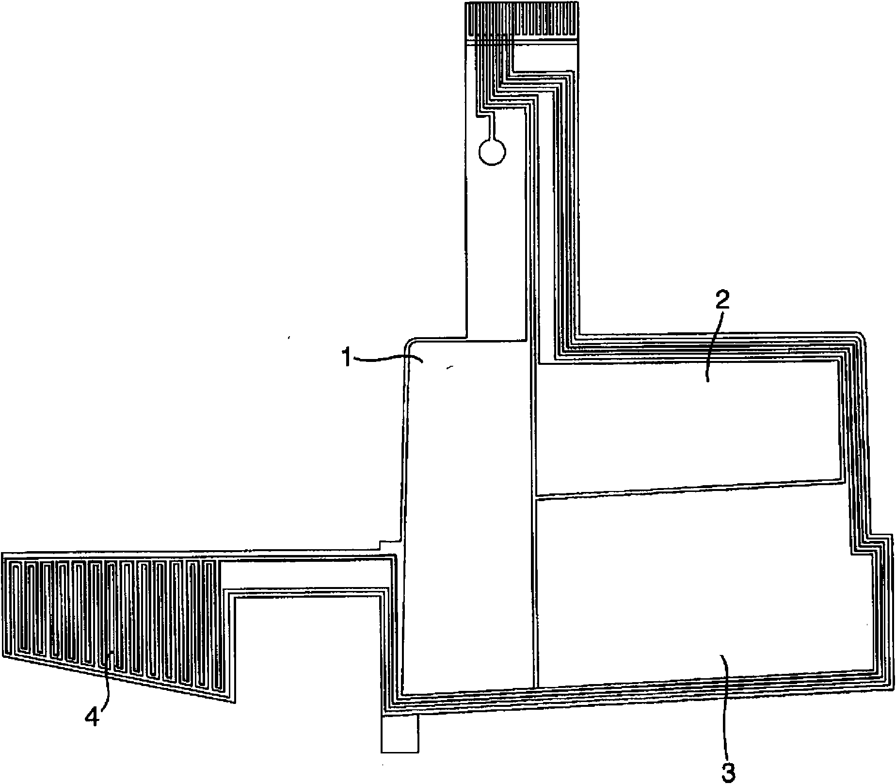
[0020] refer to figure 1 , a fluid sensor in a preferred embodiment comprises an array of conductive plates in the basic layout shown in the figure. Located on the front side of the array are conductive plates 1 to 4 configured as thin strips. These strips have a height designed to cover the height of the container in both the vertical and horizontal orientations of the container. The conductive strips 1 to 4 are preferably made of thin flexible metallic material and are separated from each other by insulating material. The strips are mounted on a conventional flexible circuit board, which is not described in detail here.

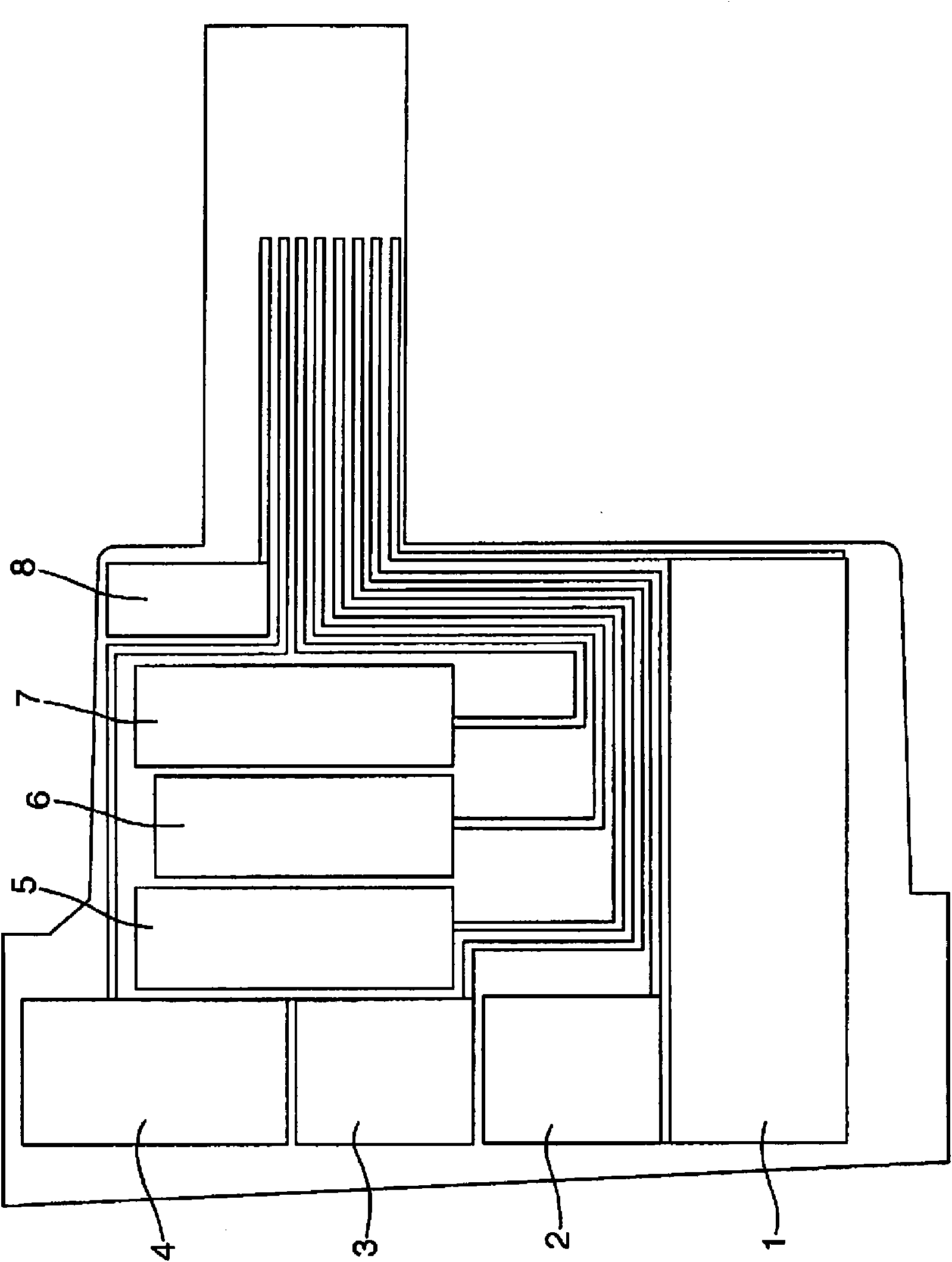
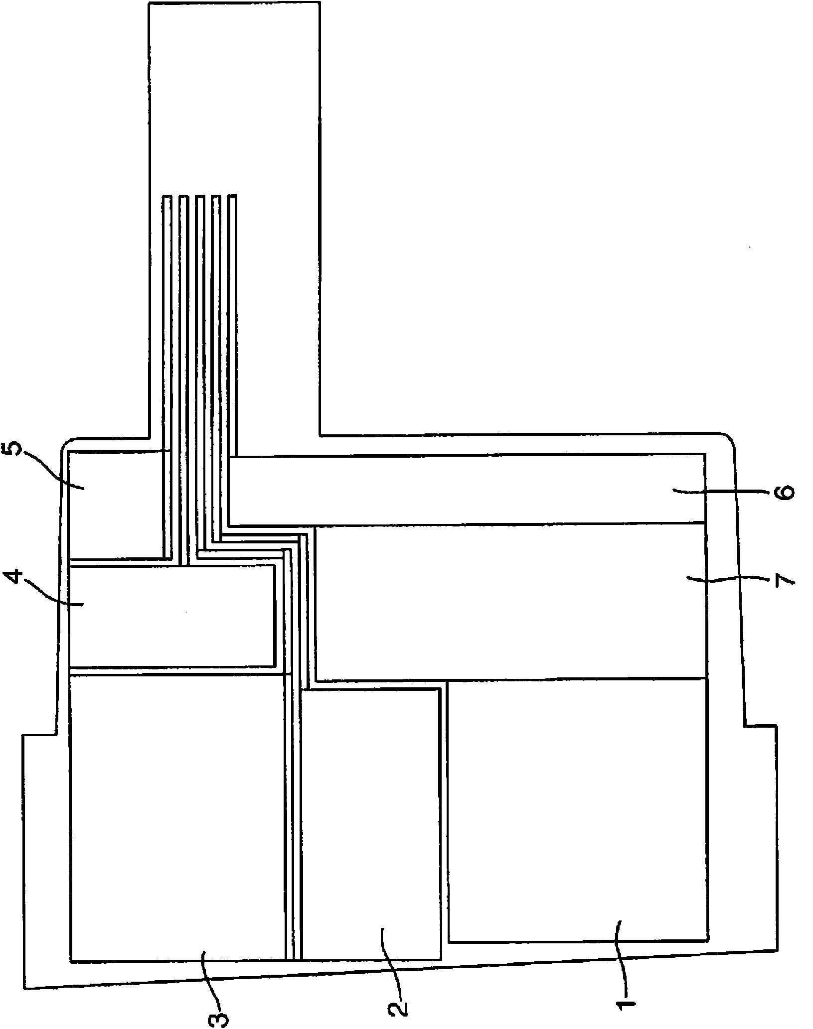
[0021] There is no limit to the number of conductive plates that can be used, as in the Figures 2 to 5 The different arrangements of fluid sensors shown in are illustrated in . Furthermore, depending on the container size and shape, the conductive plates may even be in the shape of thin strips, thin lines or even points. Figures 9a to 9d Shows the po...


PUM


Abstract

A fluid level sensor to determine the level of fluid into a container used in negative pressure wound therapy. The sensor includes an array of conductive plates to produce electric field lines throughthe container and fluid within, the plates serving as the plates of a capacitor. The plates (1-4), are located close to the wall of the container, and are connected to a circuit board, electronics and software to determine the fluid level in the container based on the relative changes of capacitance between the plates. The capacitance is converted into a voltage signal representative of the change. The algorithms are designed to check the fluid level over predefined time periods to indicate the fluid level at more than one point and also track the fluid level. The fluid sensor can be used inthe vertical, horizontal or other position of the container as desired.

Description

technical field [0001] The present invention relates to a fluid level sensor, and more particularly, to a fluid level sensor for determining the level or flow rate of a fluid into a container used in negative pressure wound therapy. This technique uses a pump to apply negative pressure to the wound to move effluent fluid from the wound bed and maintain sub-atmospheric pressure at the wound site. Background technique [0002] Where these pump devices are used, the level of effluent fluid collected in the container must be monitored to ensure that the container is not completely filled. It is important to avoid infection of the pump unit and to ensure that the correct therapy is being applied. Due to the infectious nature of the effluent fluid and the fact that the container may be disposable, there is a significant advantage in employing a non-contact fluid level detection method. [0003] Numerous techniques exist for measuring fluid levels, including floating, contact, ul...

Claims


Application Information

Patent Timeline
Patent Type & Authority Applications(China)
IPC IPC(8): G01F23/26A61M1/00
CPCA61M1/0001G01F23/268A61M2205/3334A61M2205/3389A61M1/0088A61M1/982A61M1/60
Inventor 格雷格·巴利艾伦·比尔
Owner KCI LICENSING INC
Why Eureka
Try Eureka