Stationary fixture for pelvis biomechanics experiment
A technology of biomechanics and fixtures, applied in the field of biomechanics, can solve the problems of inconsistency in the actual physiological position of the pelvis, no correlation and continuity, and damage to the pelvic bone and structure, so as to save repetitive labor. Effect
Inactive Publication Date: 2011-01-05
BEIHANG UNIV
View PDF0 Cites 0 Cited by
- Summary
- Abstract
- Description
- Claims
- Application Information
AI Technical Summary
Problems solved by technology
(1) The fixing method of the fixture does not match the actual physiological position of the pelvis;
(2) The installation and disassembly of the fixture will damage the bone and structure of the pelvis;
(3) Some researchers mentioned in the experimental plan that the pelvis is in the standing position as the experimental posture, but the fixtures used do not have any constraints to ensure that the pelvis is in the standing position;
(4) Different researchers use different fixtures when conducting the same experiment, and the experimental results of each other are not related and continuous
Method used
View moreImage
Smart ImageViewing Examples
Examples
Embodiment Construction
Login to View More PUM
 Abstract
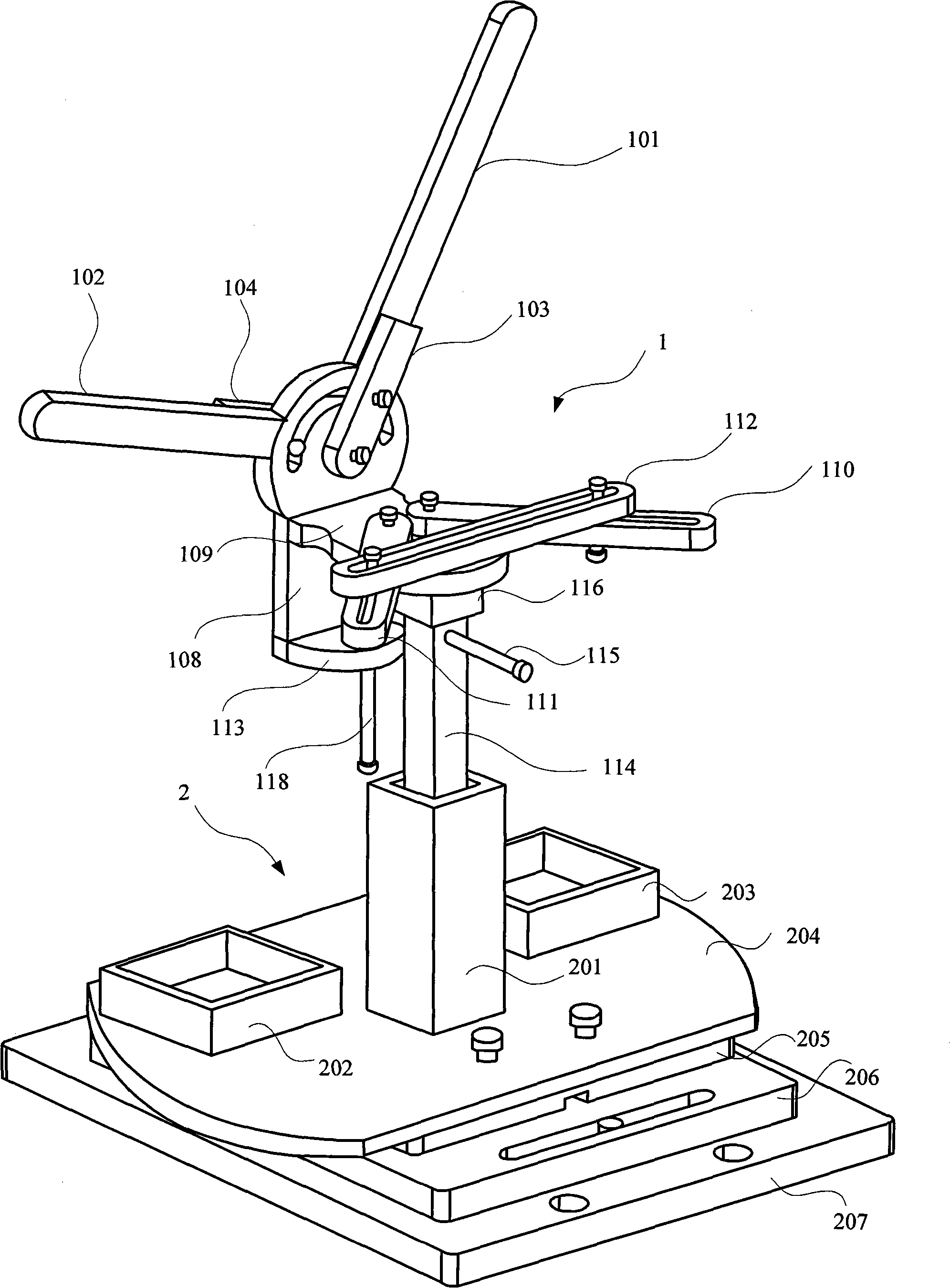
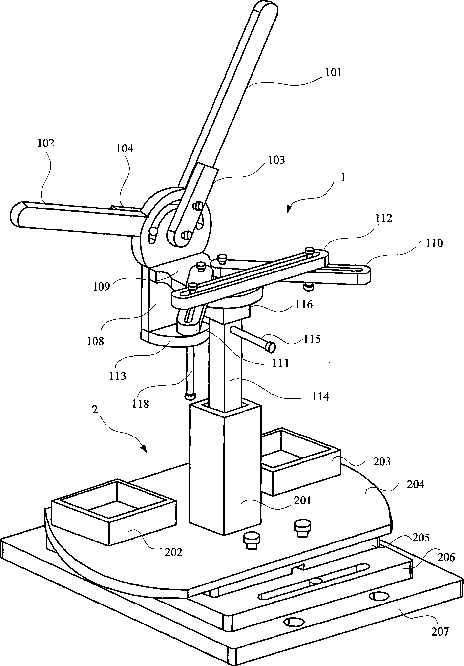
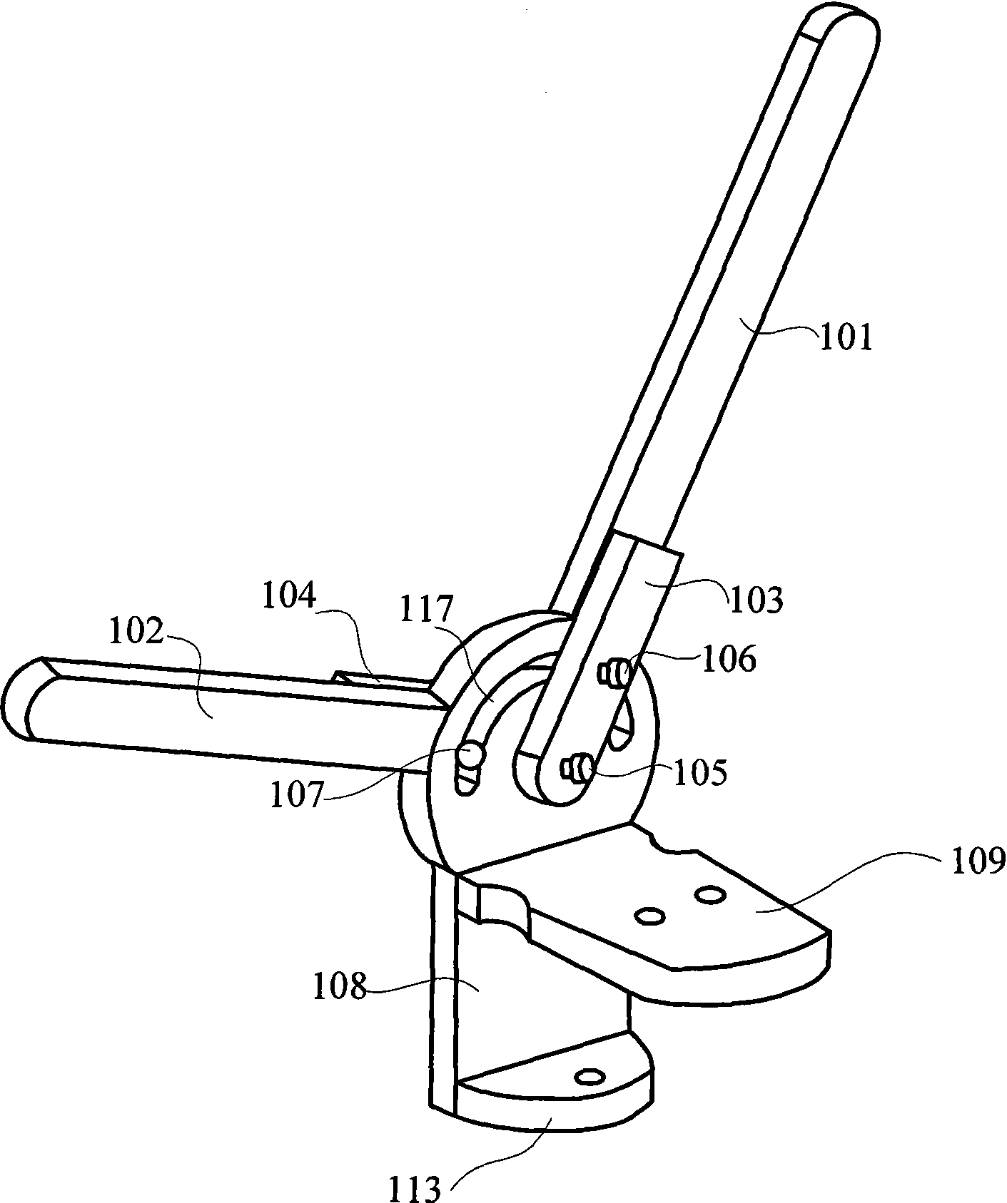
The invention discloses a stationary fixture for pelvis biomechanics experiment. The fixture is connected to a mechanical testing machine by a base. A first anterior superior iliac spine baffle and a second anterior superior iliac spine baffle of the fixture are respectively connected to a pubic tubercle baffle by a first sacrum stationary jaw and a second sacrum stationary jaw. A top tray of upper margin of pubic bone and a bottom board of lower margin of pubic bone are respectively vertically connected to the pubic tubercle baffle. The first sacrum stationary jaw and the second sacrum stationary jaw are connected to the top tray of upper margin of pubic bone. A sacrum fixing cross slab is fixed on the first sacrum stationary jaw and the second sacrum stationary jaw. A connecting rod is arranged on the lower surface of the top tray of upper margin of pubic bone. A back head of pubic bone is horizontally connected to the connecting rod. The lower head of pubic bone is vertically drilled through the bottom board of lower margin of pubic bone. With the fixture of the invention, the pelvis can be fixed by taking a standing posture to do experiment, and the substance of bone and the structure of pelvic are not destroyed by assembling or detaching the fixture.
Description
A fixed fixture for pelvic biomechanics experiment technical field The invention relates to the field of biomechanics, in particular to a fixing fixture for pelvic biomechanics experiments. The scope of application of the present invention is biomechanical experiments using the pelvic standing position as the experimental posture, and the applicable mechanical testing machine is a vertical loading mechanical testing machine. Background technique At present, there is no special general-purpose pelvic fixation fixture in the field of pelvic biomechanics experiments, and most researchers design the required pelvic fixation fixture by themselves. When different researchers conduct the same experiment, they have to use their own designed fixtures to repeat the experiments done by the predecessors before they can conduct more in-depth research. Otherwise, there is no way to compare the experimental data, resulting in a waste of manpower and material resources. References [1] Wa...
Claims
Login to View More Application Information
Patent Timeline
 Patent Type & Authority Patents(China)
IPC IPC(8): A61B19/00A61B90/00
Inventor 裴葆青徐声伟牟姣李慧
Owner BEIHANG UNIV
Features
- R&D
- Intellectual Property
- Life Sciences
- Materials
- Tech Scout
- Unparalleled Data Quality
- Higher Quality Content
- 60% Fewer Hallucinations
Learn More Browse by: Latest US Patents, China's latest patents, Technical Efficacy Thesaurus, Application Domain, Technology Topic, Popular Technical Reports.
© 2025 PatSnap. All rights reserved.Legal|Privacy policy|Modern Slavery Act Transparency Statement|Sitemap|About US| Contact US: help@patsnap.com


