Balance shaft of two-cylinder diesel
A technology for balance shafts and diesel engines, applied in the field of balance shafts, can solve problems such as two-cylinder diesel engines and single balance shafts that have not yet been seen, and achieve the effects of simple structure, simplified structure, and strong practicability
Active Publication Date: 2010-02-24
KUNMING YUNNEI POWER +1
View PDF0 Cites 0 Cited by
- Summary
- Abstract
- Description
- Claims
- Application Information
AI Technical Summary
Problems solved by technology
The function of the balance shaft of the traditional two-cylinder diesel engine is only the function of a single balance shaft
Up to now, there has not been a structure that integrates the high-pressure oil pump driving the cam and the balance weight on the two-cylinder diesel engine
Method used
View moreImage
Smart ImageViewing Examples
Examples
Embodiment Construction
[0008] Further detailed description will be made below in conjunction with the embodiments.
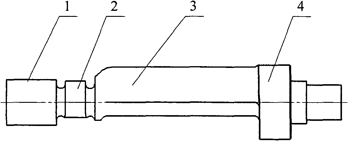
[0009] Such as figure 1 As shown, the balance shaft of the two-cylinder diesel engine proposed by the present invention has the driving cam 2 of the high-pressure oil pump on the balance shaft close to the left journal 1, and has a balance between the driving cam of the high-pressure oil pump and the right journal 4. Heavy 3.
Login to View More PUM
 Abstract
The invention relates to a balance shaft of a two-cylinder diesel, a driving cam 2 of a high-pressure oil pump is arranged near the left shaft neck 1 of the balance shaft, and a balance weight 3 is arranged between the driving cam and the right shaft neck 4 of the high-pressure oil pump; the balance shaft of a two-cylinder diesel can meet the requirements of high rotation and high load for the diesel, and can reduce the vibration and noise of the two-cylinder diesel; simultaneously, the balance shaft integrated with the driving cam and the balance weight of the high-pressure oil pump of the diesel not only meets the balance requirement of the two-cylinder diesel, but also realizes the function of the driving high-pressure oil pump; and the invention improves the comfort of the diesel and decreases the cost of the diesel, and has simple structure, easy production and processing and high practicality.
Description
technical field [0001] The invention relates to a balance shaft of an engine, in particular to a balance shaft of a two-cylinder diesel engine. Background technique [0002] In order to meet the vibration and smoothness requirements of the diesel engine, a balance shaft needs to be added to the two-cylinder diesel engine to reduce the vibration and noise of the whole machine. The function of the balance shaft of the traditional two-cylinder diesel engine is only the function of a single balance shaft. So far, there has not been a structure integrating a high-pressure oil pump driving a cam and a balance weight on a two-cylinder diesel engine. Contents of the invention [0003] The object of the present invention is to provide a balance shaft of a two-cylinder diesel engine, which not only meets the requirements of the two-cylinder diesel engine to reduce the vibration and noise of the whole machine, but also drives the high-pressure oil pump of the diesel engine, so as to...
Claims
Login to View More Application Information
Patent Timeline
 Patent Type & Authority Applications(China)
IPC IPC(8): F16F15/26
Inventor 张学文杨永忠
Owner KUNMING YUNNEI POWER
- R&D Engineer
- R&D Manager
- IP Professional
- Industry Leading Data Capabilities
- Powerful AI technology
- Patent DNA Extraction
Learn More Browse by: Latest US Patents, China's latest patents, Technical Efficacy Thesaurus, Application Domain, Technology Topic, Popular Technical Reports.
© 2024 PatSnap. All rights reserved.Legal|Privacy policy|Modern Slavery Act Transparency Statement|Sitemap|About US| Contact US: help@patsnap.com


